3M MP220 Installation Guide - Page 2
Display - manual
 |
View all 3M MP220 manuals
Add to My Manuals
Save this manual to your list of manuals |
Page 2 highlights
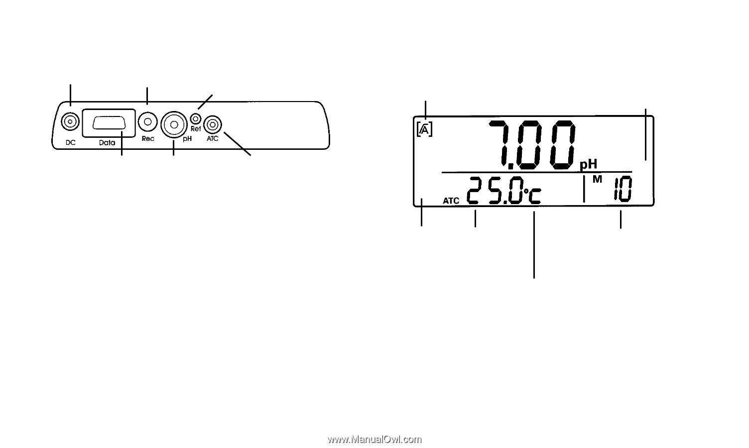
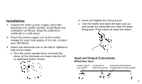
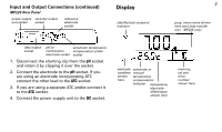
Input and Output Connections (continued) MP225 Rear Panel power supply recorder output unit socket socket reference electrode socket Display stability/auto endpoint indicator 2 prog. menu icons shown here (and data transfer icon - MP225 only) data output socket pH or automatic temperature combination compensation probe electrode socket socket 1. Disconnect the shorting clip from the pH socket and retain it by clipping it over the socket. 2. Connect the electrode to the pH socket. If you are using an electrode incorporating ATC connect the other lead to the ATC socket. 3. If you are using a separate ATC probe connect it to the ATC socket. 4. Connect the power supply unit to the DC socket. electrode automatic or condition manual shown temperature here compensation indicator temperature, electrode offset/slope shown here memory, cal and error number shown here
-
 1
1 -
 2
2 -
 3
3 -
 4
4 -
 5
5 -
 6
6 -
 7
7 -
 8
8 -
9
-
10
-
11
-
12
-
13
-
14
-
15
 |
 |