3M MP8640 Operation Guide - Page 19
Connection to Signal Terminals
 |
UPC - 051125589963
View all 3M MP8640 manuals
Add to My Manuals
Save this manual to your list of manuals |
Page 19 highlights
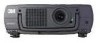
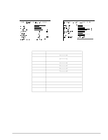
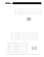
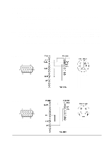
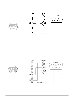
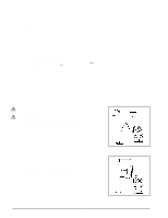
Section 5: Connection to Signal Terminals 5.1 Connection to the Video Signal Terminal a. Input signal S-VIDEO signal Luminance signal Chrominance signal VIDEO signal Input AUDIO signal Output 1.0Vp-p, 75 Ω termination 0.286Vp-p (burst signal), 75 Ω termination 1.0Vp-p, 75Ω termination 200mVrms, 20 kΩ below (MAX 3.0Vp-p) 0~200mVrms, 1k Ω b. Signal input terminal Chrominance signal Luminance signal Note: Ground Ground S VIDEO input (Mini DIN4 pin) Video input signal terminals have priority in the following order: 1. S-VIDEO input terminal 2. RCA jack (composite) input terminal 5.2 Connection to the RGB Signal Terminal a. Input signal / Output signal Video signal Analog 0.7Vp-p 75 Ω termination (Positive polarity) Horizontal sync signal TTL level (Positive/negative polarity) Vertical sync signal TTL level (Positive/negative polarity) Composite sync signal TTL level Input 200mVrms, 20k Ω below (MAX 3.0Vp-p) Audio signal Output 0 ∼ 200mVrms, 1k Ω b. Signal input terminal / output terminal 1 Video signal (Red) 9 N.C 2 Video signal (Green) 10 Ground 3 Video signal (Blue) 11 Ground 4 N.C 12 N.C 5 N.C 13 Horizontal/Composite sync signal 6 Ground (for R) 14 Vertical sync signal 7 Ground (for G) 15 N.C 8 Ground (for B) D-sub 15pin (Male) © 3M 1997 3M™ Multimedia Projector MP8640 19
-
 1
1 -
2
-
3
-
4
-
5
-
6
-
7
-
8
-
9
-
10
-
11
-
12
-
13
-
 14
14 -
 15
15 -
 16
16 -
 17
17 -
 18
18 -
 19
19 -
 20
20 -
 21
21 -
 22
22 -
 23
23 -
 24
24 -
25
-
26
-
27
-
28
 |
 |