3Ware 9500S-4LP Installation Guide - Page 21
Additional Details About the LED Status Connectors - raid card
 |
UPC - 693494950045
View all 3Ware 9500S-4LP manuals
Add to My Manuals
Save this manual to your list of manuals |
Page 21 highlights
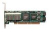
Installing a Serial ATA RAID Controller LED indicators for individual drives on J7 and J8 Overall LED drive status indicator: the last two pins of J7. The anode is the lower of the two pins and the cathode is the upper. I2C Serial ports are double- connector stacked connectors. Odd-numbered ports 1 through 7 are located below even-numbered ports 0 through 6. Ports: 6 and 7 4 and 5 2 and 3 Serial number (on plate) 0 and 1 SODIMM (memory module) BBU (Battery Backup Unit) connector LED connector details J7 is for drives 0, 1, 2, 3 (left to right) The last two pins on J8 is for drives 4, 5, 6, 7 (left to right) J7 and J8 are unused. Figure 2. 8-Port 3ware 9500S-8 Serial ATA RAID Controller, Pchip v1.5 (BBU-compatible) Additional Details About the LED Status Connectors As shown in Figures 1 through 5, LED connectors for individual drives are on J7, J8, and J9 for the full size cards, and on J3 for the half-size 4-port card. Pin 1 is located in the lower left-hand corner of each 10-pin connector. The odd-numbered pins, located on the bottom row, are 3.3V for the anode side of each LED to be connected. The evennumbered pins are the return or cathode side. Table 1 summarizes the LED indicator pin positions for the different controllers. www.3ware.com 13
-
 1
1 -
2
-
3
-
4
-
5
-
6
-
7
-
8
-
9
-
10
-
11
-
12
-
13
-
14
-
15
-
 16
16 -
 17
17 -
 18
18 -
 19
19 -
 20
20 -
 21
21 -
 22
22 -
 23
23 -
 24
24 -
 25
25 -
 26
26 -
27
-
28
-
29
-
30
-
31
-
32
-
33
-
34
-
35
-
36
-
37
-
38
-
39
-
40
-
41
-
42
-
43
-
44
-
45
-
46
-
47
-
48
-
49
-
50
-
51
-
52
-
53
-
54
-
55
-
56
-
57
-
58
-
59
-
60
-
61
-
62
-
63
-
64
-
65
-
66
-
67
-
68
-
69
-
70
-
71
-
72
-
73
-
74
-
75
-
76
-
77
-
78
-
79
-
80
-
81
-
82
-
83
-
84
-
85
-
86
-
87
-
88
-
89
-
90
-
91
-
92
-
93
-
94
-
95
-
96
-
97
-
98
-
99
-
100
-
101
-
102
-
103
-
104
-
105
-
106
-
107
-
108
-
109
-
110
-
111
-
112
-
113
-
114
-
115
-
116
-
117
-
118
-
119
-
120
-
121
-
122
-
123
-
124
-
125
-
126
 |
 |
