3Ware 9500S-4LP Installation Guide - Page 24
To connect serial cables to the controller, proper orientation and installation - sata 2
 |
UPC - 693494950045
View all 3Ware 9500S-4LP manuals
Add to My Manuals
Save this manual to your list of manuals |
Page 24 highlights
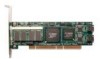
Installing the Hardware LED indicators for individual drives on J3: 0, 1, 2, 3 (left to right) Overall LED drive status indicator: the last two pins of J3. The anode is the lower of the two pins and the cathode is the upper. I2C connector Serial ports are double-stacked connectors. Oddnumbered ports 1 and 3 are located below evennumbered ports 0 and 2. Ports: 2 and 3 0 and 1 Serial number (on plate) SODIMM (memory module) BBU (Battery Backup Unit) connector Figure 4. 4-Port 3ware 9500S-4 Serial ATA RAID Controller To connect serial cables to the controller 1 Take out the serial cables provided with the 3ware SATA RAID controller. 3ware serial controllers are supplied with serial interface cables, one for each port on the controller. One edge of each interface cable connector is keyed so that it can only be inserted in one direction. This helps to ensure proper orientation and installation 2 Align the cable connector with the connector on the controller, matching the slotted key and carefully mate the connectors. 16 3ware 9000 Series Serial ATA RAID Controller Installation Guide
-
 1
1 -
2
-
3
-
4
-
5
-
6
-
7
-
8
-
9
-
10
-
11
-
12
-
13
-
14
-
15
-
16
-
17
-
18
-
 19
19 -
 20
20 -
 21
21 -
 22
22 -
 23
23 -
 24
24 -
 25
25 -
 26
26 -
 27
27 -
 28
28 -
 29
29 -
30
-
31
-
32
-
33
-
34
-
35
-
36
-
37
-
38
-
39
-
40
-
41
-
42
-
43
-
44
-
45
-
46
-
47
-
48
-
49
-
50
-
51
-
52
-
53
-
54
-
55
-
56
-
57
-
58
-
59
-
60
-
61
-
62
-
63
-
64
-
65
-
66
-
67
-
68
-
69
-
70
-
71
-
72
-
73
-
74
-
75
-
76
-
77
-
78
-
79
-
80
-
81
-
82
-
83
-
84
-
85
-
86
-
87
-
88
-
89
-
90
-
91
-
92
-
93
-
94
-
95
-
96
-
97
-
98
-
99
-
100
-
101
-
102
-
103
-
104
-
105
-
106
-
107
-
108
-
109
-
110
-
111
-
112
-
113
-
114
-
115
-
116
-
117
-
118
-
119
-
120
-
121
-
122
-
123
-
124
-
125
-
126
 |
 |
