ASRock 775S61 User Manual - Page 15
Jumpers Setup
 |
View all ASRock 775S61 manuals
Add to My Manuals
Save this manual to your list of manuals |
Page 15 highlights
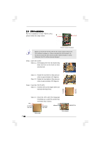
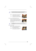
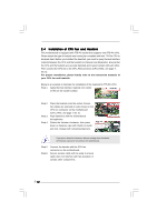
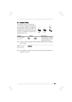
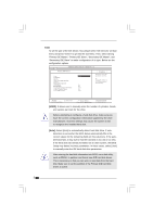
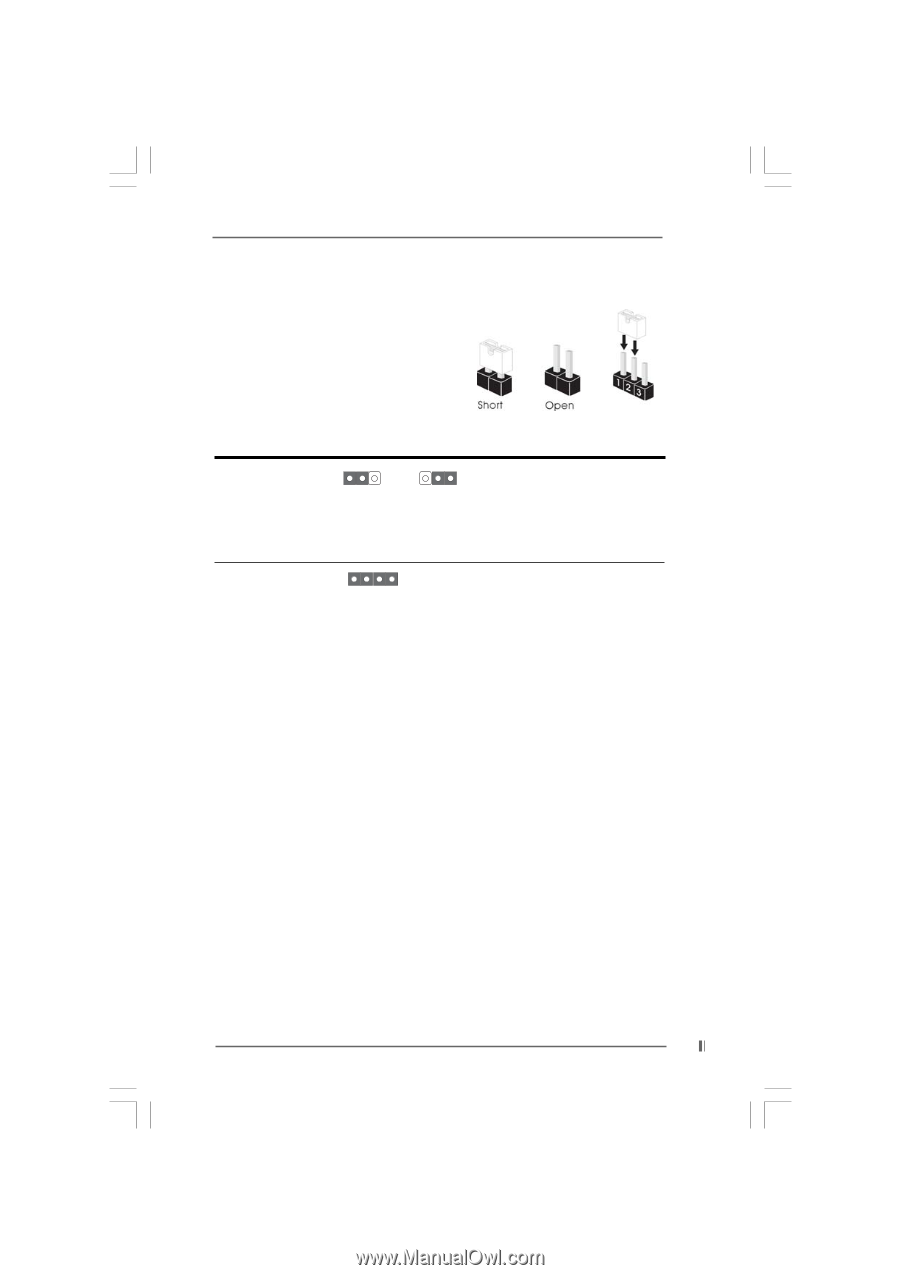
2.7 Jumpers Setup The illustration shows how jumpers are setup. When the jumper cap is placed on pins, the jumper is "SHORT". If no jumper cap is placed on pins, the jumper is "OPEN". The illustration shows a 3-pin jumper whose pin1 and pin2 are "SHORT" when jumper cap is placed on these 2 pins. Jumper Setting Description PS2_USB_PWR1 1_2 2_3 Short pin2, pin3 to enable (see p.7 item 1) +5V +5VSB +5VSB (standby) for PS/2 or USB wake up events. Note: To select +5VSB, it requires 2 Amp and higher standby current provided by power supply. JR1(see p.7 item 21) JL1(see p.7 item 21) JR1 JL1 Note: If the jumpers JL1 and JR1 are short, both front panel and rear panel audio connectors can work. 15
-
 1
1 -
2
-
3
-
4
-
5
-
6
-
7
-
8
-
9
-
 10
10 -
 11
11 -
 12
12 -
 13
13 -
 14
14 -
 15
15 -
 16
16 -
 17
17 -
 18
18 -
 19
19 -
 20
20 -
21
-
22
-
23
-
24
-
25
-
26
-
27
-
28
-
29
-
30
-
31
 |
 |
15
15
15
15
15
2.7 Jumpers Setup
2.7 Jumpers Setup
2.7 Jumpers Setup
2.7 Jumpers Setup
2.7 Jumpers Setup
The illustration shows how jumpers are
setup. When the jumper cap is placed on
pins, the jumper is “SHORT”. If no jumper cap
is placed on pins, the jumper is “OPEN”. The
illustration shows a 3-pin jumper whose pin1
and pin2 are “SHORT” when jumper cap is
placed on these 2 pins.
Jumper
Setting
Description
PS2_USB_PWR1
Short pin2, pin3 to enable
(see
p.7
item 1)
+5VSB (standby) for PS/2 or
USB wake up events.
Note:
To select +5VSB, it requires 2 Amp and higher standby current provided by
power supply.
JR1
(see
p.7 item 21)
JL1
(see
p.7 item 21)
Note:
If the jumpers JL1 and JR1 are short, both front panel and rear panel audio
connectors can work.
+
5V
1
_
2
+
5VSB
2
_
3
J
R1
J
L1