ASRock 775S61 User Manual - Page 16
Onboard Headers and Connectors
 |
View all ASRock 775S61 manuals
Add to My Manuals
Save this manual to your list of manuals |
Page 16 highlights
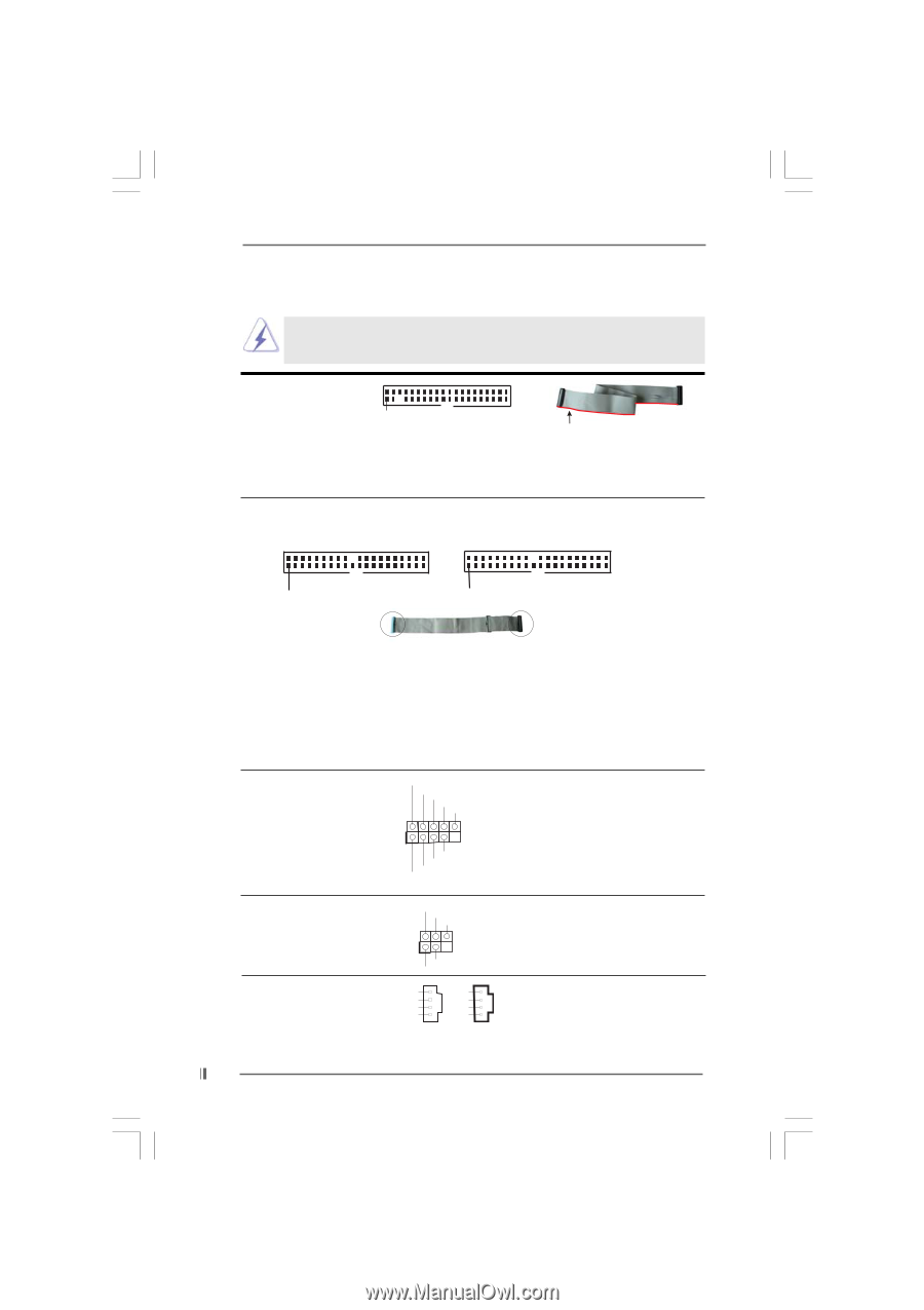
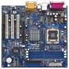
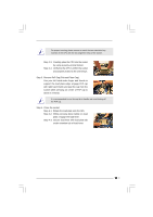
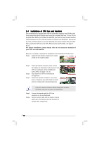
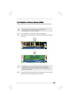
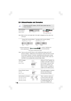
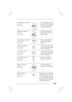
2.8 Onboard Headers and Connectors Connectors are NOT jumpers. DO NOT place jumper caps over these connectors. FDD Connector (33-pin FLOPPY1) (see p.7, No. 19) Pin1 FLOPPY1 the red-striped side to Pin1 Note: Make sure the red-striped side of the cable is plugged into Pin1 side of the connector. Primary IDE Connector (Blue) Secondary IDE Connector (Black) (39-pin IDE1, see p.7, No. 9) (39-pin IDE2, see p.7, No. 8) PIN1 IDE1 PIN1 IDE2 connect the blue end to the motherboard connect the black end to the IDE devices 80-conductor ATA 66/100/133 cable Note: If you use only one IDE device on this motherboard, please set the IDE device as "Master". Please refer to the instruction of your IDE device vendor for the details. Besides, to optimize compatibility and performance, please connect your hard disk drive to the primary IDE connector (IDE1, blue) and CD-ROM to the secondary IDE connector (IDE2, black). USB 2.0 Header (9-pin USB45) (see p.7, No. 16) USB_PWR P-5 P+5 GND DUMMY 1 GND P+4 P-4 USB_PWR ASRock I/O PlusTM provides you 6 ready-to-use USB 2.0 ports on the rear panel. If the rear USB ports are not sufficient, this USB 2.0 header is available to support 2 extra USB 2.0 ports. Infrared Module Header (5-pin IR1) (see p.7, No. 14) IRTX +5V DUMMY 1 GND IRRX Internal Audio Connectors (4-pin CD1, 4-pin AUX1) (CD1: see p.7, No. 23) (AUX1: see p.7, No. 24) AUX-R GND GND AUX-L CD-R GND GND CD-L AUX1 CD1 16 This header supports an optional wireless transmitting and receiving infrared module. These connectors allow you to receive stereo audio input from sound sources such as a CD-ROM, DVD-ROM, TV tuner card, or MPEG card.
-
 1
1 -
2
-
3
-
4
-
5
-
6
-
7
-
8
-
9
-
10
-
 11
11 -
 12
12 -
 13
13 -
 14
14 -
 15
15 -
 16
16 -
 17
17 -
 18
18 -
 19
19 -
 20
20 -
 21
21 -
22
-
23
-
24
-
25
-
26
-
27
-
28
-
29
-
30
-
31
 |
 |