ASRock 775S61 User Manual - Page 17
ATX 12V Connector
 |
View all ASRock 775S61 manuals
Add to My Manuals
Save this manual to your list of manuals |
Page 17 highlights
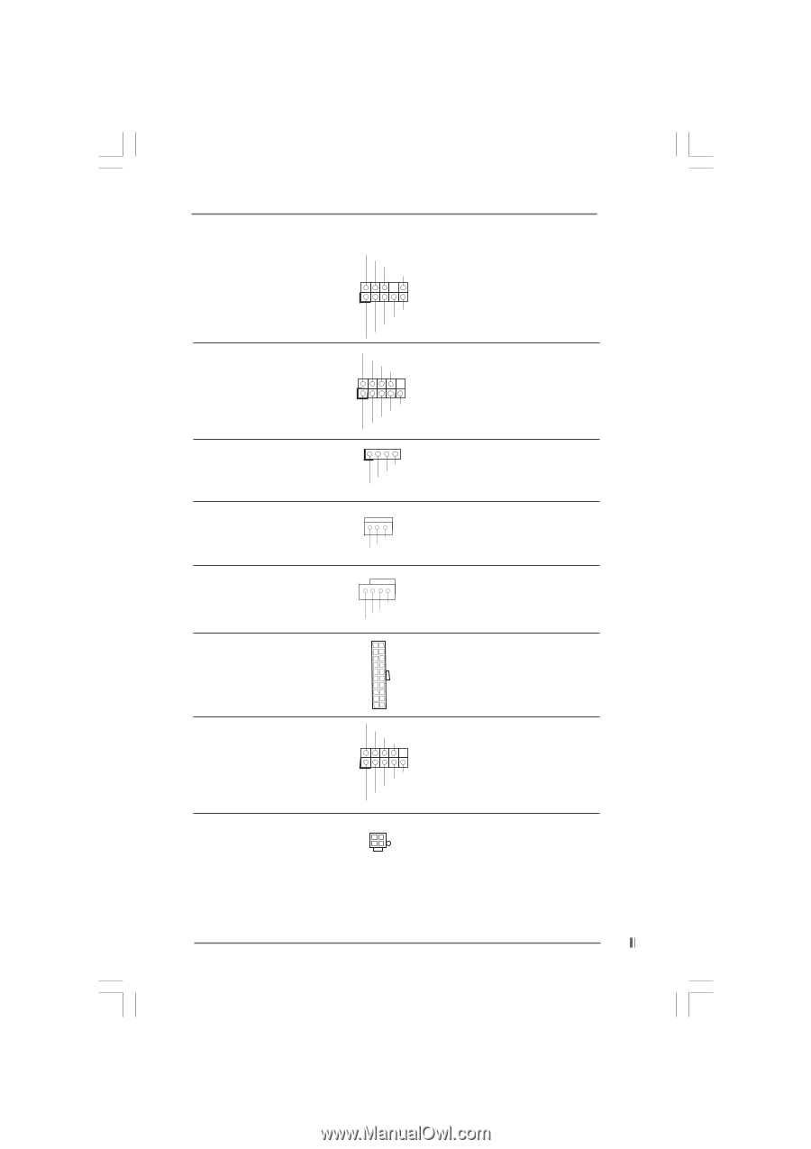
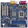
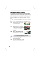
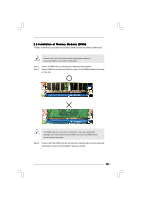
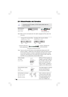
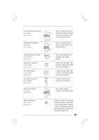
Front panel audio connector (9-pin AUDIO1) (see p.7 item 22) System panel connector (9-pin PANEL1) (see p.7 item 12) Chassis speaker connector (4-pin SPEAKER 1) (see p.7 item 13) GND +5VA BACKOUT-R BACKOUT-L 1 A U D - O U T- L GND A U D - O U T- R MIC-POWER MIC PLED+ PLEDPWRBTN# GND 1 DUMMY RESET# GND HDLEDHDLED+ 1 SPEAKER DUMMY DUMMY +5V This is an interface for front panel audio cable that allows convenient connection and control of audio devices. This connector accommodates several system front panel functions. This connector allows you to attach to the chassis speaker. Chassis fan connector (3-pin CHA_FAN1) (see p.7 item 11) GND +12V CHA_FAN_SPEED Connect the fan cable to the connector matching the black wire to the ground pin. CPU fan connector (4-pin CPU_FAN1) (see p.7 item 5) ATX power connector (20-pin ATXPWR1) (see p.7 item 7) GND +12V CPU_FAN_SPEED N/C Connect the fan cable to the connector matching the black wire to the ground pin. Connect an ATX power supply to the connector. Serial port connector (9-pin COM1) (see p.7 item 15) ATX 12V Connector (4-pin ATX12V1) (see p.7 No. 2) RRXD1 DDTR#1 DDSR#1 CCTS#1 1 RRI#1 RRTS#1 GND TTXD1 DDCD#1 This COM1 connector supports a serial port module. Please note that it is necessary to connect a power supply with ATX 12V plug to this connector so that it can provides sufficient power. Failing to do so will cause the failure to power up. 17
-
 1
1 -
2
-
3
-
4
-
5
-
6
-
7
-
8
-
9
-
10
-
11
-
 12
12 -
 13
13 -
 14
14 -
 15
15 -
 16
16 -
 17
17 -
 18
18 -
 19
19 -
 20
20 -
 21
21 -
 22
22 -
23
-
24
-
25
-
26
-
27
-
28
-
29
-
30
-
31
 |
 |