ASRock ALiveXFire-eSATA2 R3.0 User Manual - Page 20
Install the standard Radeon CrossFire
 |
View all ASRock ALiveXFire-eSATA2 R3.0 manuals
Add to My Manuals
Save this manual to your list of manuals |
Page 20 highlights
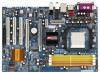
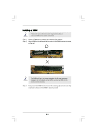
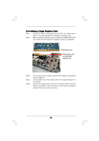
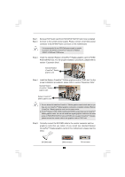
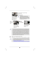
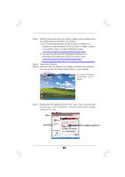
Step 1. Step 2. Remove PCIE Switch card from PCIE2/PCIE SWITCH slot if one is installed. Connect to the system power supply. Please connect a hard disk power connector to SLI/XFIRE Power connector on this motherboard. It is recommended to use 500-Watt power supply or greater to perform the benefit of CrossFireTM feature for Radeon X850XT, X1900 and X1950 series. Step 3. Install the standard Radeon (CrossFireTM Ready) graphics card to PCIE2/ PCIE SWITCH slot. For the proper installation procedures, please refer to section "Expansion Slots". Standard Radeon (CrossFireTM Ready) graphics card Step 4. Install the Radeon CrossFireTM Edition graphics card to PCIE3 slot. For the proper installation procedures, please refer to section "Expansion Slots". Standard Radeon (CrossFireTM Ready) graphics card Radeon CrossFireTM Edition graphics card 1. You are allowed to install two CrossFireTM Edition graphics cards to both slots, or you may use one CrossFireTM Edition graphics cards and a compatible standard Radeon (CrossFireTM Ready) graphics card from the same series. 2. For ATITM Radeon X1300, X1600, X1650 and X1950Pro series, there are no CrossFireTM Edition graphics cards. You can still install two regular graphics cards from the same series on PCIE2/PCIE SWITCH slot and PCIE3 slot to support CrossFireTM. Besides, please connect the monitor cable to the graphics card on PCIE3 slot. Step 5. Correctly connect the DVI-DMS cable to the monitor connector and two graphics cards that you install. (If you install two standard Radeon (CrossFireTM Ready) graphics cards to this motherboard, please skip this step.) DVI-DMS cable DMS connector 20 DVI connector
-
 1
1 -
2
-
3
-
4
-
5
-
6
-
7
-
8
-
9
-
10
-
11
-
12
-
13
-
14
-
 15
15 -
 16
16 -
 17
17 -
 18
18 -
 19
19 -
 20
20 -
 21
21 -
 22
22 -
 23
23 -
 24
24 -
 25
25 -
26
-
27
-
28
-
29
-
30
-
31
-
32
-
33
-
34
-
35
-
36
-
37
-
38
-
39
-
40
-
41
-
42
-
43
-
44
-
45
-
46
-
47
-
48
-
49
-
50
-
51
-
52
-
53
-
54
-
55
-
56
-
57
-
58
-
59
-
60
 |
 |
