ASRock ALiveXFire-eSATA2 R3.0 User Manual - Page 5
Introduction - bios
 |
View all ASRock ALiveXFire-eSATA2 R3.0 manuals
Add to My Manuals
Save this manual to your list of manuals |
Page 5 highlights
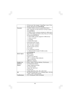
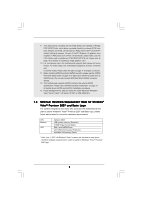
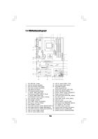
1. Introduction Thank you for purchasing ASRock ALiveXFire-eSATA2 motherboard, a reliable motherboard produced under ASRock's consistently stringent quality control. It delivers excellent performance with robust design conforming to ASRock's commitment to quality and endurance. In this manual, chapter 1 and 2 contain introduction of the motherboard and step-bystep guide to the hardware installation. Chapter 3 and 4 contain the configuration guide to BIOS setup and information of the Support CD. Because the motherboard specifications and the BIOS software might be updated, the content of this manual will be subject to change without notice. In case any modifications of this manual occur, the updated version will be available on ASRock website without further notice. You may find the latest VGA cards and CPU support lists on ASRock website as well. ASRock website http://www.asrock.com If you require technical support related to this motherboard, please visit our website for specific information about the model you are using. www.asrock.com/support/index.asp 1.1 Package Contents 1 x ASRock ALiveXFire-eSATA2 Motherboard (ATX Form Factor: 12.0-in x 8.2-in, 30.5 cm x 20.8 cm) 1 x ASRock ALiveXFire-eSATA2 Quick Installation Guide 1 x ASRock ALiveXFire-eSATA2 Support CD 1 x Ultra ATA 66/100/133 IDE Ribbon Cable (80-conductor) 1 x 3.5-in Floppy Drive Ribbon Cable 2 x Serial ATA (SATA) Data Cables (Optional) 1 x Serial ATA (SATA) HDD Power Cable (Optional) 1 x HDMI_SPDIF Cable (Optional) 1 x ASRock 6CH_eSATAII I/O Shield 1 x USB Bracket 1 x PCIE Switch Card This motherboard is bundled with one PCIE Switch card installed on PCIE2/ PCIE SWITCH slot, which allows you better flexibility to choose PCIE functions between one PCIE x16 slot and two PCIE slots for ATITM CrossFireTM without setting up jumpers. 5
-
 1
1 -
 2
2 -
 3
3 -
 4
4 -
 5
5 -
 6
6 -
 7
7 -
 8
8 -
 9
9 -
 10
10 -
 11
11 -
12
-
13
-
14
-
15
-
16
-
17
-
18
-
19
-
20
-
21
-
22
-
23
-
24
-
25
-
26
-
27
-
28
-
29
-
30
-
31
-
32
-
33
-
34
-
35
-
36
-
37
-
38
-
39
-
40
-
41
-
42
-
43
-
44
-
45
-
46
-
47
-
48
-
49
-
50
-
51
-
52
-
53
-
54
-
55
-
56
-
57
-
58
-
59
-
60
 |
 |