ASRock AM2V890-VSTA Quick Installation Guide - Page 2
Motherboard L, Motherboard Layout, ayout
 |
View all ASRock AM2V890-VSTA manuals
Add to My Manuals
Save this manual to your list of manuals |
Page 2 highlights
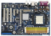
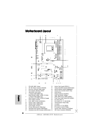
Motherboard Layout English 1 PS2_USB_PWR1 Jumper 16 System Panel Header (PANEL1) 2 ATX 12V Power Connector (ATX12V1) 17 Primary Serial ATA Connector (SATA1, black) 3 CPU Fan Connector (CPU_FAN1) 18 Chassis Speaker Header (SPEAKER 1) 4 CPU Heatsink Retention Module 19 Chassis Fan Connector (CHA_FAN1) 5 AM2 940-Pin CPU Socket 20 Flash Memory 6 2 x 240-pin DDRII DIMM Slots 21 Floppy Connector (FLOPPY1) (Dual Channel A: DDRII_1, DDRII_2; Yellow) 22 Game Port Header (GAME1) 7 2 x 240-pin DDRII DIMM Slots 23 HDMI_SPDIF Header (HDMI_SPDIF1) (Dual Channel B: DDRII_3, DDRII_4; Orange) 24 Front Panel Audio Header (HD_AUDIO1) 8 North Bridge Controller 25 PCI Slots (PCI1- 3) 9 Clear CMOS Jumper (CLRCMOS1) 26 PCI Express x4 / x1 Slot (PCIE3) 10 USB 2.0 Header (USB67, Blue) 27 Infrared Module Header (IR1) 11 USB 2.0 Header (USB45, Blue) 28 J1 Jumper 12 South Bridge Controller 29 PCI Express x1 Slot (PCIE2) 13 Primary IDE Connector (IDE1, Blue) 30 PCI Express x16 Slot (PCIE1) 14 Secondary IDE Connector (IDE2, Black) 31 Internal Audio Connector: CD1 (Black) 15 Secondary Serial ATA Connector (SATA2, black) 32 ATX Power Connector (ATXPWR1) 2 ASRock AM2V890-VSTA Motherboard
-
 1
1 -
 2
2 -
 3
3 -
 4
4 -
 5
5 -
 6
6 -
 7
7 -
 8
8 -
9
-
10
-
11
-
12
-
13
-
14
-
15
-
16
-
17
-
18
-
19
-
20
-
21
-
22
-
23
-
24
-
25
-
26
-
27
-
28
-
29
-
30
-
31
-
32
-
33
-
34
-
35
-
36
-
37
-
38
-
39
-
40
-
41
-
42
-
43
-
44
-
45
-
46
-
47
-
48
-
49
-
50
-
51
-
52
-
53
-
54
-
55
-
56
-
57
-
58
-
59
-
60
-
61
-
62
-
63
-
64
-
65
-
66
-
67
-
68
-
69
-
70
-
71
-
72
-
73
-
74
-
75
-
76
-
77
-
78
-
79
-
80
-
81
-
82
-
83
-
84
-
85
-
86
-
87
-
88
-
89
-
90
-
91
-
92
-
93
-
94
-
95
-
96
-
97
-
98
-
99
-
100
-
101
-
102
-
103
-
104
-
105
-
106
-
107
-
108
-
109
-
110
-
111
-
112
-
113
-
114
-
115
-
116
-
117
-
118
-
119
-
120
-
121
-
122
-
123
-
124
-
125
-
126
-
127
-
128
 |
 |
