ASRock Fatal1ty X399 Professional Gaming User Manual - Page 17
I/O Panel, Description, Activity / Link LED, Speed LED, Status
 |
View all ASRock Fatal1ty X399 Professional Gaming manuals
Add to My Manuals
Save this manual to your list of manuals |
Page 17 highlights
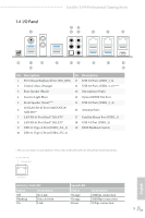
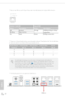
1.4 I/O Panel 1 Fatal1ty X399 Professional Gaming Series 24 35 6 7 8 19 17 16 15 14 13 12 11 9 18 10 No. Description 1 PS/2 Mouse/Keyboard Port (PS2_KB1) 2 Central / Bass (Orange) 3 Rear Speaker (Black) 4 Line In (Light Blue) 5 Front Speaker (Lime)*** 10 GLAN RJ-45 Port (AQUANTIA® 6 AQC107)** 7 LAN RJ-45 Port (Intel® I211AT)* 8 LAN RJ-45 Port (Intel® I211AT)* 9 USB 3.1 Type-A Port (USB31_TA_1) 10 USB 3.1 Type-C Port (USB31_TC_1) No. Description 11 USB 3.0 Ports (USB3_7_8) 12 USB 3.0 Ports (USB3_5_6)**** 13 Microphone (Pink) 14 Optical SPDIF Out Port 15 USB 3.0 Ports (USB3_3_4) 16 Antenna Ports 17 Fatal1ty Mouse Port (USB3_1) 18 USB 3.0 Port (USB3_2) 19 BIOS Flashback Switch * There are two LEDs on each LAN port. Please refer to the table below for the LAN port LED indications. ACT/LINK LED SPEED LED LAN Port Activity / Link LED Status Description Off Blinking On No Link Data Activity Link Speed LED Status Orange Orange Green Description 10Mbps connection 100Mbps connection 1Gbps connection 9 English
-
 1
1 -
2
-
3
-
4
-
5
-
6
-
7
-
8
-
9
-
10
-
11
-
 12
12 -
 13
13 -
 14
14 -
 15
15 -
 16
16 -
 17
17 -
 18
18 -
 19
19 -
 20
20 -
 21
21 -
 22
22 -
23
-
24
-
25
-
26
-
27
-
28
-
29
-
30
-
31
-
32
-
33
-
34
-
35
-
36
-
37
-
38
-
39
-
40
-
41
-
42
-
43
-
44
-
45
-
46
-
47
-
48
-
49
-
50
-
51
-
52
-
53
-
54
-
55
-
56
-
57
-
58
-
59
-
60
-
61
-
62
-
63
-
64
-
65
-
66
-
67
-
68
-
69
-
70
-
71
-
72
-
73
-
74
-
75
-
76
-
77
-
78
-
79
-
80
-
81
-
82
-
83
-
84
-
85
-
86
-
87
-
88
-
89
-
90
-
91
-
92
-
93
-
94
-
95
-
96
-
97
-
98
-
99
-
100
-
101
-
102
-
103
-
104
-
105
 |
 |
