ASRock Fatal1ty X399 Professional Gaming User Manual - Page 35
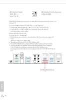
Caution, Never install the RGB, LED cable in the wrong orienta, tion; otherwise, the cable may
 |
View all ASRock Fatal1ty X399 Professional Gaming manuals
Add to My Manuals
Save this manual to your list of manuals |
Page 35 highlights
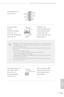
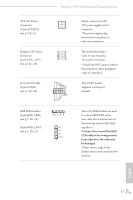
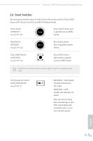
Fatal1ty X399 Professional Gaming Series ATX 12V Power Connector (4-pin ATX12V2) (see p.7, No. 2) Graphics 12V Power Connector (6-pin GFX_12V1) (see p.7, No. 18) 4 1 6 3 Serial Port Header (9-pin COM1) (see p.7, No. 29) RRXD1 DDTR#1 DDSR#1 CCTS#1 1 RRI#1 RRTS#1 GND TTXD1 DDCD#1 RGB LED Headers (4-pin RGB_LED1) (see p.7, No. 28) (4-pin RGB_LED2) (see p.7, No. 12) 1 12V G R B B R G 12V 1 Please connect an ATX 12V power supply to this connector. *The power supply plug fits into this connector in only one orientation. This motherboard provides a 6-pin Graphics 12V power connector. * Install the PSU's power cable to this connector when 4 graphics cards are installed. This COM1 header supports a serial port module. These two RGB headers are used to connect RGB LED extension cable which allows users to choose from various LED lighting effects. Caution: Never install the RGB LED cable in the wrong orientation; otherwise, the cable may be damaged. *Please refer to page 64 for further instructions on these two headers. English 27
-
 1
1 -
2
-
3
-
4
-
5
-
6
-
7
-
8
-
9
-
10
-
11
-
12
-
13
-
14
-
15
-
16
-
17
-
18
-
19
-
20
-
21
-
22
-
23
-
24
-
25
-
26
-
27
-
28
-
29
-
 30
30 -
 31
31 -
 32
32 -
 33
33 -
 34
34 -
 35
35 -
 36
36 -
 37
37 -
 38
38 -
 39
39 -
 40
40 -
41
-
42
-
43
-
44
-
45
-
46
-
47
-
48
-
49
-
50
-
51
-
52
-
53
-
54
-
55
-
56
-
57
-
58
-
59
-
60
-
61
-
62
-
63
-
64
-
65
-
66
-
67
-
68
-
69
-
70
-
71
-
72
-
73
-
74
-
75
-
76
-
77
-
78
-
79
-
80
-
81
-
82
-
83
-
84
-
85
-
86
-
87
-
88
-
89
-
90
-
91
-
92
-
93
-
94
-
95
-
96
-
97
-
98
-
99
-
100
-
101
-
102
-
103
-
104
-
105
 |
 |
