ASRock Fatal1ty X99X Killer/3.1 User Manual - Page 34
Smart Switches
 |
View all ASRock Fatal1ty X99X Killer/3.1 manuals
Add to My Manuals
Save this manual to your list of manuals |
Page 34 highlights
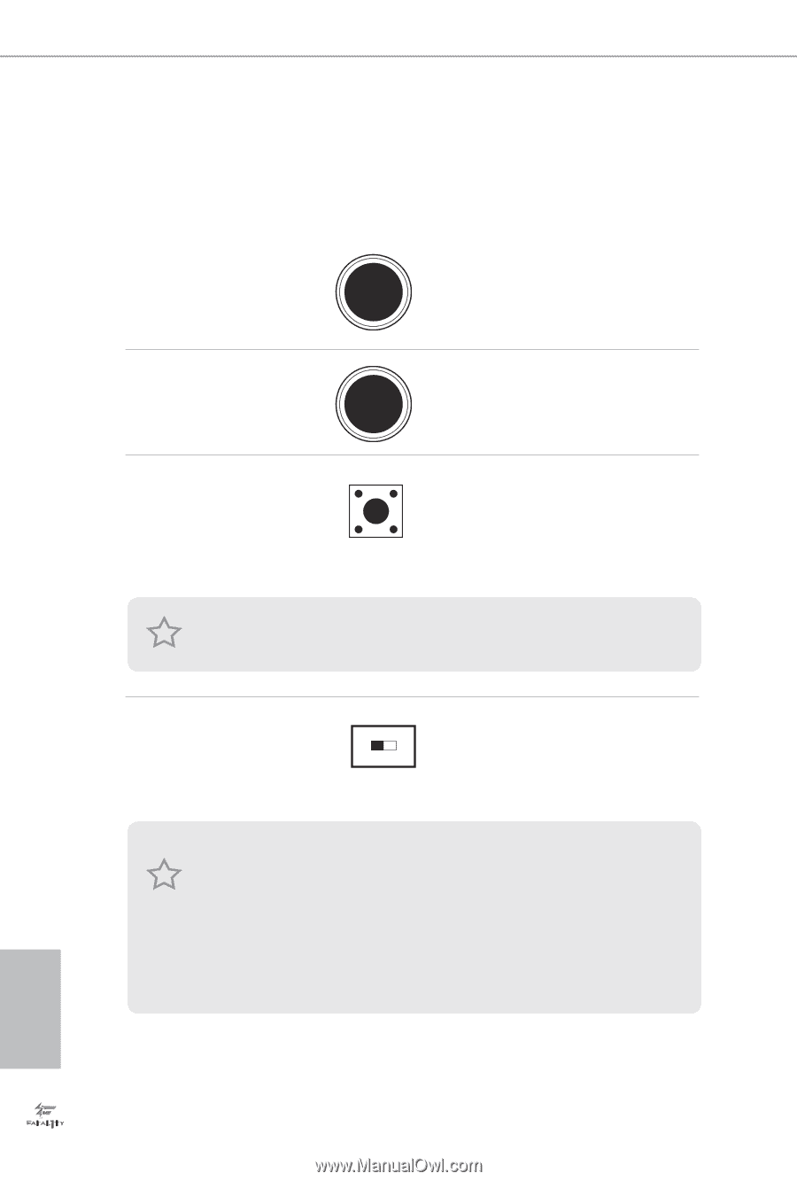
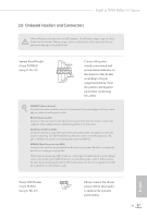
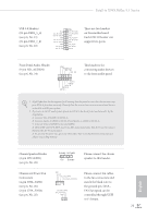
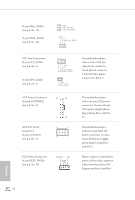
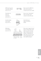
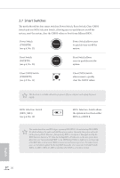
2.7 Smart Switches he motherboard has four smart switches: Power Switch, Reset Switch, Clear CMOS Switch and one BIOS Selection Switch, allowing users to quickly turn on/of the system, reset the system, clear the CMOS values or boot from diferent BIOS. Power Switch (PWRBTN) (see p.6, No. 22) Power Power Switch allows users to quickly turn on/of the system. Reset Switch (RSTBTN) (see p.6, No. 23) Reset Reset Switch allows users to quickly reset the system. Clear CMOS Switch (CLRCBTN) (see p.9, No. 14) Clear CMOS Switch allows users to quickly clear the CMOS values. his function is workable only when you power of your computer and unplug the power supply. BIOS Selection Switch (BIOS_SEL1) (see p.6, No. 19) AB BIOS Selection Switch allows the system to boot from either BIOS A or BIOS B. his motherboard has two BIOS chips, a primary BIOS (BIOS_A) and a backup BIOS (BIOS_ B), which enhances the safety and stability of your system. Normally, the system will work on the primary BIOS. However, if the primary BIOS is corrupted or damaged, just lip the BIOS Selection Switch to "B", then the backup BIOS will take over on the next system boot. Ater that, use "Secure Backup UEFI" in the UEFI Setup Utility to duplicate a working copy of the BIOS iles to the primary BIOS to ensure normal system operation. For safety issues, users are not able to update the backup BIOS manually. Users may refer to the BIOS LEDs (BIOS_A_LED or BIOS_B_LED) to identify which BIOS is currently activated. English 26
-
 1
1 -
2
-
3
-
4
-
5
-
6
-
7
-
8
-
9
-
10
-
11
-
12
-
13
-
14
-
15
-
16
-
17
-
18
-
19
-
20
-
21
-
22
-
23
-
24
-
25
-
26
-
27
-
28
-
 29
29 -
 30
30 -
 31
31 -
 32
32 -
 33
33 -
 34
34 -
 35
35 -
 36
36 -
 37
37 -
 38
38 -
 39
39 -
40
-
41
-
42
-
43
-
44
-
45
-
46
-
47
-
48
-
49
-
50
-
51
-
52
-
53
-
54
-
55
-
56
-
57
-
58
-
59
-
60
-
61
-
62
-
63
-
64
-
65
-
66
-
67
-
68
-
69
-
70
-
71
-
72
-
73
-
74
-
75
-
76
-
77
-
78
-
79
-
80
-
81
-
82
-
83
-
84
-
85
-
86
-
87
-
88
-
89
-
90
-
91
-
92
-
93
-
94
-
95
-
96
-
97
-
98
-
99
-
100
-
101
-
102
-
103
-
104
-
105
-
106
-
107
-
108
-
109
-
110
 |
 |