ASRock Fatal1ty X99X Killer/3.1 User Manual - Page 49
HDD Saver Cable Installation Guide
 |
View all ASRock Fatal1ty X99X Killer/3.1 manuals
Add to My Manuals
Save this manual to your list of manuals |
Page 49 highlights
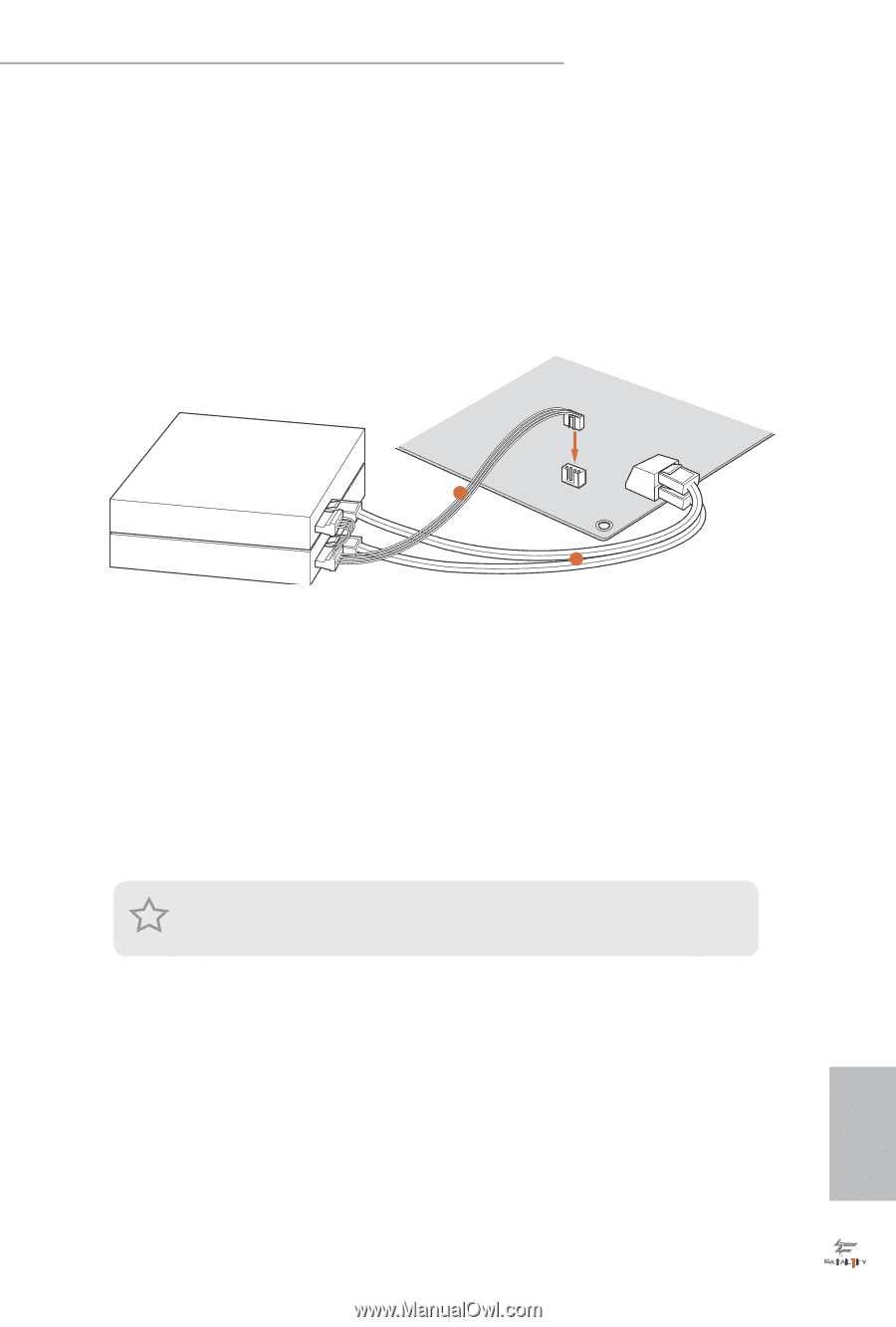
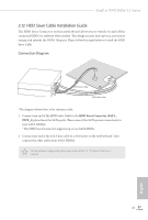
Fatal1ty X99X Killer/3.1 Series 2.12 HDD Saver Cable Installation Guide The HDD Saver Connector on this motherboard allows you to switch on and off the connected HDDs via sotware when needed. his design secures more privacy, saves more energy, and extends the HDDs' lifespans. Please follow the steps below to install the HDD Saver Cable. Connection Diagram 1 HDD Saver Cable 2 SATA data cable *he diagram shown here is for reference only. 1. Connect one end of the HDD Saver Cable to the HDD Saver Connector (SATA_ PWR_1) placed near the SATA ports. hen connect the SATA power connector(s) to your SATA HDD(s). * he HDD Saver Connector supports up to two SATA HDDs. 2. Connect one end of the SATA data cable to a SATA port on the motherboard. hen connect the other end to your SATA HDD(s). For the sotware coniguration, please refer to the section 3.2 "F-Stream" in this user manual. 41 English
-
 1
1 -
2
-
3
-
4
-
5
-
6
-
7
-
8
-
9
-
10
-
11
-
12
-
13
-
14
-
15
-
16
-
17
-
18
-
19
-
20
-
21
-
22
-
23
-
24
-
25
-
26
-
27
-
28
-
29
-
30
-
31
-
32
-
33
-
34
-
35
-
36
-
37
-
38
-
39
-
40
-
41
-
42
-
43
-
 44
44 -
 45
45 -
 46
46 -
 47
47 -
 48
48 -
 49
49 -
 50
50 -
 51
51 -
 52
52 -
 53
53 -
 54
54 -
55
-
56
-
57
-
58
-
59
-
60
-
61
-
62
-
63
-
64
-
65
-
66
-
67
-
68
-
69
-
70
-
71
-
72
-
73
-
74
-
75
-
76
-
77
-
78
-
79
-
80
-
81
-
82
-
83
-
84
-
85
-
86
-
87
-
88
-
89
-
90
-
91
-
92
-
93
-
94
-
95
-
96
-
97
-
98
-
99
-
100
-
101
-
102
-
103
-
104
-
105
-
106
-
107
-
108
-
109
-
110
 |
 |