ASRock G PRO User Manual
ASRock G PRO Manual
 |
View all ASRock G PRO manuals
Add to My Manuals
Save this manual to your list of manuals |
ASRock G PRO manual content summary:
- ASRock G PRO | User Manual - Page 1
G Pro / GV Pro User Manual Published October 2002 Copyright©2002 ASRock INC. All rights reserved. 1 - ASRock G PRO | User Manual - Page 2
part of this manual may be reproduced, transcribed, transmitted, or translated in any language, in any form or by any means, except duplication of documentation by the purchaser for backup purpose, without written consent of ASRock Inc. Products and corporate names appearing in this guide may or may - ASRock G PRO | User Manual - Page 3
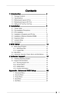
Specifications 4 1.3 Motherboard Layout (G Pro 6 1.4 Motherboard Layout (GV Pro 7 1.5 ASRock I/OTM (G Pro / GV Pro 8 2 Installation 9 2.1 Screw Holes 9 2.2 Pre-installation Precautions 9 2.3 CPU Installation 9 2.4 Installation of Heatsink and CPU fan 10 2.5 Installation of Memory Modules - ASRock G PRO | User Manual - Page 4
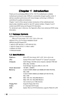
) ASRock G Pro / GV Pro Quick Installation Guide ASRock Intel-SiS Support CD 1 cable for IDE devices (1 x ATA 66/100/133) 1 cable for floppy drive (1 x ribbon cable) 1 ASRock I/O shield 1 COM port bracket 1.2 Specifications Platform: CPU: Chipsets: Clock Generator: Memory: IDE: Floppy Port: Audio - ASRock G PRO | User Manual - Page 5
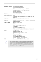
port: ECP/EPP support Audio Jack: Line Out/ Line In/ Microphone + Game port BIOS: AMI legal BIOS Supports "Plug and Play" ACPI 1.1 compliance wake up events Supports jumperfree SMBIOS 2.3.1 support CPU frequency stepless control (only for advanced users' reference) OS: Windows 98SE / ME - ASRock G PRO | User Manual - Page 6
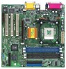
1.3 Motherboard Layout (G Pro) 22 3 21 45 6 24.4cm (9.6 in) PS/2 Mouse PS/2 Keyboard Chipset 01 23 01 23 AUX1 CD1 27 20 19 AUDIO1 AUDIO CODEC Super I/O Accelerated Graphics Port PCI 1 PCI 2 11 2MB PCI 3 BIOS AMR1 SiS South Bridge CMOS 9 Battery CHA_FAN1 CLRCMOS1 FLOPPY1 - ASRock G PRO | User Manual - Page 7
Motherboard Layout (GV Pro) AUDIO CODEC Super I/O PCI 1 PCI 2 11 2MB PCI 3 BIOS AMR1 GV PRO SiS South Bridge CMOS 9 Battery CHA_FAN1 CLRCMOS1 FLOPPY1 IR1 COM1 USB45 SPEAKER1 RESET HDLED PANEL1 PWRBTN PLED 10 14 15 12 26 1 ATX power connector (ATXPWR1) 2 CPU socket 3 CPU - ASRock G PRO | User Manual - Page 8
1.5 ASRock I/OTM (G Pro / GV Pro) 1 Parallel port 2 RJ-45 port 3 Game port 4 Microphone (Pink) 5 Line In (Light Blue) 6 Line Out (Lime) 7 USB 2.0 ports 8 VGA port 9 PS/2 keyboard port (Purple) 10 PS/2 mouse port (Green) 8 - ASRock G PRO | User Manual - Page 9
G Pro / GV Pro is a Micro ATX form factor (9.6" x 9.6", 24.4 x 24.4 cm) motherboard. Before you install the motherboard, study the configuration of your chassis to ensure that the motherboard fits into it. Make sure to unplug the power cord before installing or removing the motherboard. Failure - ASRock G PRO | User Manual - Page 10
good contact with each other. For proper installation, please kindly refer to the instruction manuals of vendors of CPU fan and heatsink. 2.5 Installation of Memory Modules (DIMM) SDRAM (Synchronous DRAM) DIMM (Dual In-line Memory Module) has 168 pins and DDR (Double Data Rate) SDRAM DIMM has 184 - ASRock G PRO | User Manual - Page 11
DIMM is properly seated. 2.6 Expansion Slots (PCI, AMR, and AGP Slots) There are 3 PCI slots and 1 AMR slot on both G Pro and GV Pro motherboards. Additionally, there is one AGP slot on G Pro. PCI slots: PCI slots are used to install expansion cards that have the 32-bit PCI interface. AMR slot: AMR - ASRock G PRO | User Manual - Page 12
with Pin1 Primary IDE connector (Blue) (39-pin IDE1) (see p.6/p.7 item 7) Secondary IDE connector (Black) (39-pin IDE2) (see p.6/p.7 item 8) PIN1 IDE1 Connect to the motherboard Blue PIN1 IDE2 Black Connect to the IDE devices 80-Pin ATA 100/133 cable 12 - ASRock G PRO | User Manual - Page 13
connector (IDE2, black). USB header (9-pin USB45) (see p.6/p.7 item 13) ASRock I/OTM already provided 4 default USB ports. If the 4-USB ports on p.6/p.7 item 14) This connector supports an optional wireless transmitting and receiving infrared module. Internal audio connectors (4-pin CD1, 4-pin - ASRock G PRO | User Manual - Page 14
CPU fan connector (3-pin CPU_FAN1) (see p.6/p.7 item 3) ATX power connector (20-pin ATXPWR1) (see p.6/p.7 item 1) COM1 connector (9-pin COM1) (see p.6/p.7 matching the black wire to the ground pin. Connect an ATX power supply to the connector. This connector supports a serial port module. 14 - ASRock G PRO | User Manual - Page 15
BIOS Setup Utility. The Flash Memory on the motherboard stores the BIOS Setup Utility. When you start up the computer, there is a chance for you to run the BIOS the predetermined choices. Because the BIOS software is constantly being updated, the following BIOS setup screens and descriptions are for - ASRock G PRO | User Manual - Page 16
Update Total Memory DDR1 DDR2 SDR1 SDR2 AMIBIOS SETUP UTILITY - VERSION 3.31a Security Power Boot Exit Oct 14 2002 Mon 17:07:40 [ Setup Help ] Month: Jan - Dec Day: 01 - 31 Year: 1980 - 2099 GE-PRO BIOS L0.10 Generic-X86 2000 MHz 512 KB F23 / 08 224 MB + 32 MB Share Memory None None 256 MB / 133 - ASRock G PRO | User Manual - Page 17
may due to that the hard disk is too old or too new. If the hard disk was already formatted on an older system, the BIOS Setup may detect incorrect parameters. In these cases, select [User] to manually enter the IDE hard disk drive parameters. After entering the hard disk information into - ASRock G PRO | User Manual - Page 18
Maximum Capacity This field shows the drive's maximum capacity as calculated by the BIOS based on the drive information you entered. LBA Mode This allows user to select the LBA mode for a hard disk > 512 MB under DOS and Windows; for Netware and UNIX user, select [Off] to disable the LBA mode. Block - ASRock G PRO | User Manual - Page 19
detects installed devices. Install the necessary drivers to activate the devices. 4.2.3 Utilities Menu The Utilities Menu shows the applications software that the motherboard supports. Click on a specific item then follow the installation wizard to install it. 4.2.4 ASRock PC-DIY Live Demo Program - ASRock G PRO | User Manual - Page 20
host frequency automatically. [Manual]: This allows user to set CPU host frequency manually. However, this is not recommended unless user thoroughly knows the feature. Wrong setup may cause problems during operation. SDRAM Frequency: [Auto]: The motherboard detects the memory module(s) inserted and - ASRock G PRO | User Manual - Page 21
: Use this to enable or disable support to emulate legacy I/O devices such as mouse, keyboard,... etc. PCI expansion cards' specifications require other settings. Primary Graphics Adapter: Select PCI, OnBoard VGA, or Add-on AGP as the primary graphics adapter. Peripheral Configuration: OnBoard FDC: - ASRock G PRO | User Manual - Page 22
disable onboard AC'97 audio feature. OnBoard MC'97 Modem: Enable or disable onboard MC'97 modem feature. System Hardware Monitor: You can check the status of the hardware on your system. It allows you to monitor the parameters for CPU temperature, Motherboard temperature, CPU fan speed, and critical - ASRock G PRO | User Manual - Page 23
Check" is performed before both boot-up and BIOS setup. 3. Power Setup Menu Suspend to RAM (S3): This field allows you to select whether to auto-detect or disable the ACPI Suspend-to-RAM feature. Select [Auto] will enable this feature if the system supports it. Repost Video on S3 Resume: This - ASRock G PRO | User Manual - Page 24
Boot Mode: This mode speeds up the boot-up routine by skipping memory retestings. Boot-time Diagnostic Screen: This screen shows CPU and hardware information during Power-On-Self-Test (POST) routine. If this screen is disabled, only ASRock logo is shown during the boot up process. Boot Up Num-Lock - ASRock G PRO | User Manual - Page 25
the sub-menu, the message "Save current settings and exit" will appear. If you press , it will save the current settings and exit the BIOS SETUP Utility. Exit Discarding Changes: After you enter the submenu, the message "Quit without saving changes" will appear. If you press , you will
-
 1
1 -
 2
2 -
 3
3 -
 4
4 -
 5
5 -
 6
6 -
 7
7 -
8
-
9
-
10
-
11
-
12
-
13
-
14
-
15
-
16
-
17
-
18
-
19
-
20
-
21
-
22
-
23
-
24
-
25
 |
 |

1
G Pro / GV Pro
User Manual
Published October 2002
Copyright©2002 ASRock INC. All rights reserved.