ASRock G PRO User Manual - Page 7
Motherboard Layout GV Pro, 4 Motherboard Layout GV Pro
 |
View all ASRock G PRO manuals
Add to My Manuals
Save this manual to your list of manuals |
Page 7 highlights
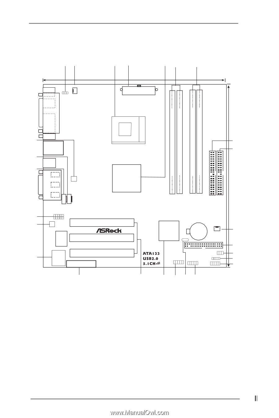
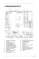
1.4 Motherboard Layout (GV Pro) 22 3 21 45 6 24.4cm (9.6 in) PS/2 Mouse PS/2 Keyboard CPU_FAN1 1 PS2_USB_PWR1 ATX PWR1 PARALLEL PORT PGA478B DDR DIMM1 (64/72 bit, 184-pin module) DDR DIMM2 (64/72 bit, 184-pin module) SDR DIMM1 (64 bit, 168-pin module) SDR DIMM2 (64 bit, 168-pin module) IDE2 IDE1 24.4cm (9.6 in) VGA GGAAMMEE AAUUDDIIOO11 21 LAN USB01 24 USB23 23 Line out LLIinninee in MMIniicc in LAN PHY AUX1 CD1 8 7 SiS 650 Series Chipset 01 23 01 23 20 AUDIO1 19 AUDIO CODEC Super I/O PCI 1 PCI 2 11 2MB PCI 3 BIOS AMR1 GV PRO SiS South Bridge CMOS 9 Battery CHA_FAN1 CLRCMOS1 FLOPPY1 IR1 COM1 USB45 SPEAKER1 RESET HDLED PANEL1 PWRBTN PLED 10 14 15 12 26 1 ATX power connector (ATXPWR1) 2 CPU socket 3 CPU fan connector (CPU_FAN1) 4 North Bridge controller 5 184-pin DDR DIMM slots (blue) 6 168-pin SDRAM DIMM slots (black) 7 Primary IDE connector (IDE1, blue) 8 Secondary IDE connector (IDE2, black) 9 Chassis fan connector (CHA_FAN1) 10 Floppy connector (FLOPPY1) 11 Flash Memory 12 System panel connector (PANEL1) 13 USB header (USB45) 14 Infrared module connector (IR1) 18 15 16 17 18 19 20 21 22 23 24 25 26 16 25 17 13 External speaker connector (SPEAKER1) South Bridge controller Clear CMOS (CLRCMOS1) PCI slots AUDIO CODEC Front panel audio connector (AUDIO1) LAN PHY PS2_USB_PWR1 jumper Internal audio connector: AUX1(white) Internal audio connector: CD1 (black) Serial port connector (COM1) AMR slot 7
-
 1
1 -
 2
2 -
 3
3 -
 4
4 -
 5
5 -
 6
6 -
 7
7 -
 8
8 -
 9
9 -
 10
10 -
 11
11 -
 12
12 -
13
-
14
-
15
-
16
-
17
-
18
-
19
-
20
-
21
-
22
-
23
-
24
-
25
 |
 |