ASRock Penryn1600SLIX3-WiFi User Manual - Page 20
Expansion Slots PCI and PCI Express Slots, Installing an expansion card
 |
View all ASRock Penryn1600SLIX3-WiFi manuals
Add to My Manuals
Save this manual to your list of manuals |
Page 20 highlights
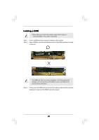
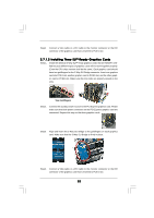
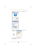
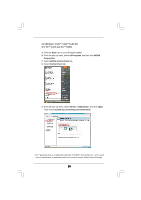
2.6 Expansion Slots (PCI and PCI Express Slots) There are 2 PCI slots and 5 PCI Express slots on this motherboard. PCI Slots: PCI slots are used to install expansion cards that have the 32-bit PCI interface. PCIE Slots: PCIE1 / PCIE3 (PCIE x16 slot) is used for PCI Express cards with x16 lane width graphics cards. For the information of the compatible SLITM or 3-Way SLITM Mode PCI Express VGA cards, please refer to the "Supported PCI Express VGA Card List for SLITM Mode" and "Supported PCI Express VGA Card List for 3-Way SLITM Mode" on page 10. PCIE2 / PCIE4 (PCIE x1 slot) is used for PCI Express cards with x1 lane width cards, such as Gigabit LAN card, SATA2 card, etc. PCIE5 (PCIE x8 slot) is used to install PCI Express expansion cards to support 3-Way SLITM function. For the information of the compatible 3-Way SLITM Mode PCI Express VGA cards, please refer to the "Supported PCI Express VGA Card List for 3-Way SLITM Mode" on page 10. 1. This motherboard supports NVIDIA® SLITM and 3-Way SLITM technology. If you want to use SLITM function, please install two identical SLITM graphics cards on PCIE1 and PCIE3 slots. If you want to use 3-Way SLITM function, please install three identical 3-Way SLITM support graphics cards on PCIE1, PCIE3 and PCIE5 slots. 2. If you plan to install only one PCI Express VGA card on this motherboard, please install it on PCIE1 slot. 3. If you want to use ASRock DeskExpress function on this motherboard, please install ASRock PCIE_DE card on PCIE4 slot. Installing an expansion card Step 1. Before installing the expansion card, please make sure that the power supply is switched off or the power cord is unplugged. Please read the documentation of the expansion card and make necessary hardware settings for the card before you start the installation. Step 2. Remove the system unit cover (if your motherboard is already installed in a chassis). Step 3. Remove the bracket facing the slot that you intend to use. Keep the screws for later use. Step 4. Align the card connector with the slot and press firmly until the card is completely seated on the slot. Step 5. Fasten the card to the chassis with screws. Step 6. Replace the system cover. 20
-
 1
1 -
2
-
3
-
4
-
5
-
6
-
7
-
8
-
9
-
10
-
11
-
12
-
13
-
14
-
 15
15 -
 16
16 -
 17
17 -
 18
18 -
 19
19 -
 20
20 -
 21
21 -
 22
22 -
 23
23 -
 24
24 -
 25
25 -
26
-
27
-
28
-
29
-
30
-
31
-
32
-
33
-
34
-
35
-
36
-
37
-
38
-
39
-
40
-
41
-
42
-
43
-
44
-
45
-
46
-
47
-
48
-
49
-
50
-
51
-
52
-
53
-
54
-
55
-
56
-
57
-
58
-
59
-
60
-
61
-
62
-
63
-
64
 |
 |