ASRock Penryn1600SLIX3-WiFi User Manual - Page 27
Onboard Headers and Connectors
 |
View all ASRock Penryn1600SLIX3-WiFi manuals
Add to My Manuals
Save this manual to your list of manuals |
Page 27 highlights
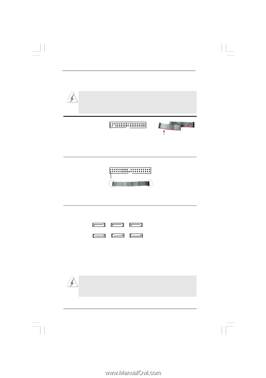
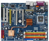
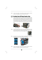
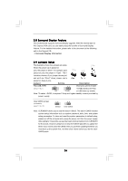
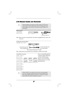
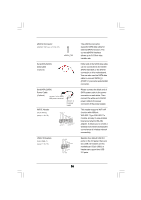
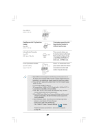
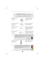
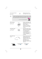
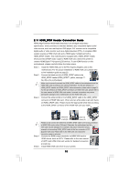
2.10 Onboard Headers and Connectors Onboard headers and connectors are NOT jumpers. Do NOT place jumper caps over these headers and connectors. Placing jumper caps over the headers and connectors will cause permanent damage of the motherboard! FDD connector (33-pin FLOPPY1) (see p.11 No. 25) Pin1 FLOPPY1 the red-striped side to Pin1 Note: Make sure the red-striped side of the cable is plugged into Pin1 side of the connector. Primary IDE connector (Blue) (39-pin IDE1, see p.11 No. 8) PIN1 connect the blue end IDE1 connect the black end to the motherboard to the IDE devices 80-conductor ATA 66/100/133 cable Note: Please refer to the instruction of your IDE device vendor for the details. Serial ATAII Connectors These six Serial ATAII (SATAII) (SATAII_1 (PORT1.0): connectors support SATA data see p.11, No. 16) cables for internal storage (SATAII_2 (PORT1.1): devices. The current SATAII see p.11, No. 10) SATAII_2(PORT1.1) SATAII_4(PORT2.1) SATAII_6(PORT3.1) interface allows up to 3.0 Gb/s (SATAII_3 (PORT2.0): data transfer rate. see p.11, No. 15) SATAII_1(PORT1.0) SATAII_3(PORT2.0) SATAII_5(PORT3.0) (SATAII_4 (PORT2.1): see p.11, No. 11) (SATAII_5 (PORT3.0): see p.11, No. 14) (SATAII_6 (PORT3.1): see p.11, No. 12) SATAII_6 (PORT3.1) connector can be used for internal storage device or be connected to eSATAII connector to support eSATAII device. Please read "eSATAII Interface Introduction" on page 33 for details about eSATAII and eSATAII installation procedures. 27
-
 1
1 -
2
-
3
-
4
-
5
-
6
-
7
-
8
-
9
-
10
-
11
-
12
-
13
-
14
-
15
-
16
-
17
-
18
-
19
-
20
-
21
-
 22
22 -
 23
23 -
 24
24 -
 25
25 -
 26
26 -
 27
27 -
 28
28 -
 29
29 -
 30
30 -
 31
31 -
 32
32 -
33
-
34
-
35
-
36
-
37
-
38
-
39
-
40
-
41
-
42
-
43
-
44
-
45
-
46
-
47
-
48
-
49
-
50
-
51
-
52
-
53
-
54
-
55
-
56
-
57
-
58
-
59
-
60
-
61
-
62
-
63
-
64
 |
 |