Acer Altos G510 Altos G510 User's Guide
Acer Altos G510 Manual
 |
View all Acer Altos G510 manuals
Add to My Manuals
Save this manual to your list of manuals |
Acer Altos G510 manual content summary:
- Acer Altos G510 | Altos G510 User's Guide - Page 1
Acer Altos G510 series User's guide - Acer Altos G510 | Altos G510 User's Guide - Page 2
Acer Altos G510 series User's guide 2nd Issue: January 2002 Changes may be made periodically to the information in this publication without obligation to notify any person of such revision or changes. Such changes will be incorporated in new editions of this manual information. No part of this - Acer Altos G510 | Altos G510 User's Guide - Page 3
for a Class B digital device pursuant to Part 15 of the FCC Rules. These limits are installed and used in accordance with the instructions, may cause harmful interference to radio be determined by turning the device off and on, the user is encouraged to try to correct the interference by one - Acer Altos G510 | Altos G510 User's Guide - Page 4
Caution! Changes or modifications not expressly approved by the manufacturer could void the user's authority, which is granted by the Federal Communications Commission, to operate this server. Use conditions This part complies with Part 15 of the FCC Rules. Operation is subject to the following two - Acer Altos G510 | Altos G510 User's Guide - Page 5
you to dangerous voltage points or other risks. Refer all servicing to qualified service personnel. 11 Unplug this product from the wall outlet and refer servicing to qualified service personnel under the following conditions: a When the power cord or plug is damaged or frayed b If liquid has been - Acer Altos G510 | Altos G510 User's Guide - Page 6
battery replacement to a qualified service technician. 13 Warning! Batteries may explode if not handled properly. Do not disassemble or dispose of them in fire. Keep them away from children and dispose of used batteries promptly. 14 Use only the proper type of power supply cord set (provided in - Acer Altos G510 | Altos G510 User's Guide - Page 7
Laser compliance statement iv Important safety instructions v 1 System tour 1 Features summary 3 External and internal structure 4 Front bezel 4 Front panel 6 Rear panel 9 Internal components 12 System boards 14 Mainboard layout 14 17 Hot Plug HDD Cage backplane board layout - Acer Altos G510 | Altos G510 User's Guide - Page 8
57 Processor Sequence 58 To install a CPU with heatsink 58 Upgrading the system memory 60 To remove a DIMM 60 To install a DIMM 61 Installing an expansion card 62 To install an expansion card 62 Installing a redundant power supply module 64 To install a redundant power supply module - Acer Altos G510 | Altos G510 User's Guide - Page 9
98 To set a Supervisor/User password 99 To change the Supervisor/User password 99 To remove the User password 99 Exit 100 Appendix A: ASM Quick Installation Guide 103 Installing ASM 105 System requirements 105 System setup 105 Appendix B: Altos G510 Rack Installation Guide107 System - Acer Altos G510 | Altos G510 User's Guide - Page 10
- Acer Altos G510 | Altos G510 User's Guide - Page 11
1 System tour - Acer Altos G510 | Altos G510 User's Guide - Page 12
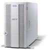
The Acer Altos G510 series server is a powerful dual-processor system loaded with a host of new and innovative features. The system offers a new standard for flexible productivity ideal for general business applications, email, web service, file clustering and print services. - Acer Altos G510 | Altos G510 User's Guide - Page 13
Hot Plug HDD cages (6 hard disk capacity) • Altos G510 Basic - one SCSI cable cage • External ports • PS/2-compatible keyboard and mouse port • Two USB ports • VGA/monitor port • Serial port • Parallel/printer port • One LAN port • Power supply unit (PSU) • Altos G510 - 450-watts redundant power - Acer Altos G510 | Altos G510 User's Guide - Page 14
(attached to the rear panel of the system). Note: Unless otherwise indicated, all front bezel features indicated on the table below apply to both the Altos G510 and Altos G510 Basic models. No. Description 1 Power indicator 2 Hard disk activity indicator - Acer Altos G510 | Altos G510 User's Guide - Page 15
5 No. Description 3 System fault indicator 4 Hard disk fault indicator (for Altos G510 model only) 5 Security keylock 6 Front bezel - Acer Altos G510 | Altos G510 User's Guide - Page 16
6 Front panel 1 System tour Altos G510 model Altos G510 Basic model - Acer Altos G510 | Altos G510 User's Guide - Page 17
half-height bay 7 Altos G510 - Hot Plug HDD cage Altos G510 Basic - non-Hot Plug HDD cable cage 8 HDD carrier (for Hot Plug HDD Cage only) 9 Floppy drive Eject button 10 Floppy drive 11 Floppy drive activity indicator 12 Power button 13 Reset button 14 Power indicator 15 Hard disk - Acer Altos G510 | Altos G510 User's Guide - Page 18
up green to indicate HDD power on and lights up in red when a HDD fault occurs. 2 This indicator lights up green to indicate drive access. Note: During Rebuild, lights flash alternately red and green. Note: Feature 17 only operates when the Hot Plug HDD cage is installed and RAID configured. - Acer Altos G510 | Altos G510 User's Guide - Page 19
Rear panel 9 Altos G510 model Altos G510 Basic model - Acer Altos G510 | Altos G510 User's Guide - Page 20
indicated on the table below apply to both the Altos G510 and Altos G510 Basic models. No. Icon 1 2 Description Altos G510 model - Main power supply unit Altos G510 Basic model - Standard 450-watts PSU PS/2 keyboard port 3 PS/2 mouse port 4 USB ports 5 RDM LAN port (10 Mbps) 1 This port - Acer Altos G510 | Altos G510 User's Guide - Page 21
11 No. Icon Description 15 Rear system fan 16 Ventilation slots N kL dRNM=çê=dRNM K=o K O q K P q mpr Ñ~áäëK Q q ê~åÖÉK= - Acer Altos G510 | Altos G510 User's Guide - Page 22
12 Internal components 1 System tour Altos G510 model Altos G510 Basic model - Acer Altos G510 | Altos G510 User's Guide - Page 23
- Power supply module bay for redundant PSU 1 Altos G510 Basic model - Standard 450-watts PSU 2 Rear system fan 3 Rear system fan release latch 4 PCI bus slot 5 Mainboard 6 Air baffle 7 Power distribution board (for Altos G510 model only) 8 Hot-swap HDD SAF-TE board (for Altos G510 - Acer Altos G510 | Altos G510 User's Guide - Page 24
14 System boards 1 System tour Mainboard layout The mainboard becomes accessible once you open the system. It should look like the figure shown below - Acer Altos G510 | Altos G510 User's Guide - Page 25
Altos G510 and Altos G510 Basic models. Item BT1 BZ1 CN1 CN2 CN3 CN4 COM1 CPU1 and CPU2 DM1 - DM4 J2 J3 J4 J5 J7 J9 J10 J13 J14 Description Battery Buzzer +12V power connector ATX power connector USB ports VGA/monitor port Serial port CPU Off) Wake on LAN connector SCSI RAID card HDD LED connector - Acer Altos G510 | Altos G510 User's Guide - Page 26
SLOT6 SCSI1 U4 U12 U18 Description CPU 1 fan connector Front fan connector CPU 2 fan connector Rear system fan connector Power supply mangement cable connector (connected to PDB board) IPMB connector SCSI HDD management cable connector (conneted to Hot Plug HDD cage backplane board) Connector for - Acer Altos G510 | Altos G510 User's Guide - Page 27
Item U19 U27 U34 U45 U46 U48 U49 USB1 VRM9.1 17 Description LSI 53C1020 SCSI Chipset ServerWorks CIOBx2 chipsets (I/O bridge) ATI Rage XL VGA chipset ServerWorks CSB5 chipset (south bridge) Flash BIOS PC87414 SIO - Super I/O chipset Video RAM USB connector Onboard VRMs (Voltage Regulator Module) - Acer Altos G510 | Altos G510 User's Guide - Page 28
Hot Plug HDD Cage backplane board layout Note: The Hot Plug HDD cage board feature is only applicable to the Altos G510 model. Label 1 2 3 4 5 Description 122-pin SAF-TE connector 80-pin SCSI HDD connector 68-pin SCSI HDD connector SCSI HDD management cable connector (I2C bus) Power connector - Acer Altos G510 | Altos G510 User's Guide - Page 29
2 System setup - Acer Altos G510 | Altos G510 User's Guide - Page 30
20 2 System setup This chapter gives you instructions on how to set up the system. Procedures on how to connect peripherals are also explained. - Acer Altos G510 | Altos G510 User's Guide - Page 31
factors when choosing a site for the system: • Near a grounded power outlet • Clean and dust-free • Stable surface free from vibration • items from the package: • Acer Altos G510 series system • Acer Altos G510 series User's guide • Acer EasyBUILDTM • Acer Altos G510 series Accessory box • System - Acer Altos G510 | Altos G510 User's Guide - Page 32
test if the system is running properly. Instructions on how to connect a printer is also described here, refer to page 25. Note: Unless otherwise indicated, all illustrations shown in this section show the Altos G510 server chassis. To connect the PS/2 keyboard Plug the keyboard cable into the PS - Acer Altos G510 | Altos G510 User's Guide - Page 33
23 To connect the PS/2 mouse Plug the PS/2 mouse cable into the PS/2 mouse port located on the rear panel of the server. (green port) - Acer Altos G510 | Altos G510 User's Guide - Page 34
24 2 System setup To connect the VGA monitor To connect the VGA monitor, simply plug the monitor cable into the VGA/monitor port server. (blue port) located on the rear panel of the - Acer Altos G510 | Altos G510 User's Guide - Page 35
25 To connect a printer The system supports both parallel and serial printers. To connect a parallel printer, plug the printer cable into the parallel/ printer port server. (burgundy port) located on the rear panel of the Note: If you are using a USB printer, connect the printer cable into the - Acer Altos G510 | Altos G510 User's Guide - Page 36
setup To connect the power cable Plug the power cable into the power cable socket located on the rear panel of the server. Then plug the other end of the power cable into a power outlet. The figure below shows a complete connection of the whole system. Altos G510 model Altos G510 Basic model - Acer Altos G510 | Altos G510 User's Guide - Page 37
. The POST messages indicate if the system is running well or not. Note: The illustration below shows the Altos G510 server chassis. Note: If the system does not turn on or boot after pressing the power button, go to the next section for the possible causes of the boot failure. Aside from the POST - Acer Altos G510 | Altos G510 User's Guide - Page 38
2 System setup Power-on problems If the system does not boot after you have applied power, check the following factors that might have caused the boot failure. • The external power cable may be loosely connected. Check the power cable connection from the power source to the power cable socket on - Acer Altos G510 | Altos G510 User's Guide - Page 39
29 Operating system configuration The Acer Altos G510 series server comes with Acer EasyBUILDTM that allows you to conveniently install your to close the disc tray. 6 The Acer EasyBUILD sequence begins. Follow all onscreen instructions. For more information, refer to the EasyBUILDTM Installation - Acer Altos G510 | Altos G510 User's Guide - Page 40
rear panel for fast network connection. To connect to the network, simply plug the network cable into the Gigabit LAN port (gray port). Note: The illustration below shows the Altos G510 server chassis. Note: Consult the operating system manual for information on how to configure the network setup. - Acer Altos G510 | Altos G510 User's Guide - Page 41
mounted system to rack-model design. To purchase a rack mount kit, contact your local Acer representative. The figure below shows the server in a rack-mount position. Note: The illustration below shows the Altos G510 server chassis. Rack Mount instructions are provided as an appendix to this manual. - Acer Altos G510 | Altos G510 User's Guide - Page 42
Down..., select Shut down from the drop-down window then click on OK. You can then turn off all peripherals connected to your server. If you are unable to shutdown the server within Windows, press and hold the power button for at least four seconds to force quit all applications and shut down. - Acer Altos G510 | Altos G510 User's Guide - Page 43
33 - Acer Altos G510 | Altos G510 User's Guide - Page 44
34 2 System setup - Acer Altos G510 | Altos G510 User's Guide - Page 45
3 Upgrading the system - Acer Altos G510 | Altos G510 User's Guide - Page 46
36 3 Upgrading the system This chapter discusses the precautionary measures and installation procedures you need to know when upgrading the system. - Acer Altos G510 | Altos G510 User's Guide - Page 47
along with preinstallation and post-installation instructions. ESD precautions Electrostatic discharge (ESD) can damage the processors, motherboard, disk drives, expansion boards, or other components. Always observe the following precautions before you install a server component: 1 Do not remove - Acer Altos G510 | Altos G510 User's Guide - Page 48
sections for specific installation instructions on the component you want to install. Warning! Failure to properly turn off the server before you unless you are a qualified service technician. Post-installation instructions Observe the following after installing a server component: 1 See to it - Acer Altos G510 | Altos G510 User's Guide - Page 49
Refer to the following sections for instructions. Before opening the server Before opening the server, observe the following precautions: 1 Turn from the power outlets. 3 Place the system unit on a flat, stable surface. Note: The illustrations used in this section show the Altos G510 server chassis. - Acer Altos G510 | Altos G510 User's Guide - Page 50
40 3 Upgrading the system To remove the front bezel The front bezel is attached to the chassis by screwless hinges. To remove the front bezel: 1 Unlock the door with the key (when necessary). 2 Open it to more than a 45° angle. 3 Lift it up a little (1), then move it away from the chassis (2). - Acer Altos G510 | Altos G510 User's Guide - Page 51
41 To remove the inner (front) panel The inner front panel is attached to the chassis by thumb latches at the top and screwless hinges at the bottom. To remove the inner front panel: 1 Simultaneously slide the two thumb catches at the top to release the latches. 2 Open the panel 90 degrees, until it - Acer Altos G510 | Altos G510 User's Guide - Page 52
42 3 Upgrading the system To remove the side panel The side panel is attached to the server by three (non-removeable) thumbscrews. To remove the side panel: 1 Loosen the three thumbscrews located at the end of the left panel closest to the - Acer Altos G510 | Altos G510 User's Guide - Page 53
43 To remove the air baffle Remove the air baffle to allow easy access to the motherboard and system components. Follow the steps below to remove the air baffle: 1 Press the release latches on both ends of the air baffle. 2 Pull out - Acer Altos G510 | Altos G510 User's Guide - Page 54
disk carrier. Note: The Hot Plug HDD cage feature is only applicable to the Altos G510 model. To remove the Hot Plug HDD cage Important: Before detaching the Hot Plug HDD cage from the chassis, make sure to first remove all hard disks from their carriers. For instructions, refer to the succeeding - Acer Altos G510 | Altos G510 User's Guide - Page 55
from the chassis (2). To install a hard disk into the Hot Plug HDD cage hard disk carrier Note: You need not remove the Hot Plut HDD cage from the chassis to install a hard disk into the cage's hard disk carrier. 1 Press your finger to the SCSI HDD release lever (1), then pull out the hard disk - Acer Altos G510 | Altos G510 User's Guide - Page 56
46 3 Upgrading the system 2 Remove the four screws to open the hard disk carrier. Keep the screws for later use. 3 When applicable, pull out any previously installed hard disk. 4 Install a hard disk in the hard disk carrier then secure it with the four screws you have removed earlier. 5 Insert - Acer Altos G510 | Altos G510 User's Guide - Page 57
1 Detach the chassis panels and remove the air baffle. 2 Connect the following cables to the SCSI backplane board: a SCSI cable b SCSI HDD 6 pin management cable c SCSI HDD power cable 3 Insert the Hot Plug HDD cage into the housing (1), then tighten the four thumbscrews to secure it to the chassis - Acer Altos G510 | Altos G510 User's Guide - Page 58
48 3 Upgrading the system 5 Reinstall the air baffle and the chassis panels. - Acer Altos G510 | Altos G510 User's Guide - Page 59
Hot Plug HDD cable cage This section includes instructions for removing and installing the HDD cable cage as well as procedures on how to install a hard disk into the cage. Note: The HDD cable cage feature is only applicable to the Altos G510 the SCSI cable and the SCSI HDD power cable from - Acer Altos G510 | Altos G510 User's Guide - Page 60
cable cage from the chassis. To install a hard disk into the HDD cable cage 1 Remove the HDD cable cage from the chassis. Refer to the instructions in the preceding section. 2 Remove the four screws that secure a previously installed hard disk to the cage then pull it out. 3 Install a new hard - Acer Altos G510 | Altos G510 User's Guide - Page 61
panel, and air baffle. 5 Insert the HDD cable cage into the housing (1), then tighten the four thumbscrews to secure it to the chassis (2). 6 Connect the SCSI cable and the SCSI HDD power cable to the hard disk drive. 7 Reinstall the air baffle and the chassis panels. - Acer Altos G510 | Altos G510 User's Guide - Page 62
52 3 Upgrading the system Installing and removing storage devices The system supports one 3.5-inch and two 5.25-inch internal storage devices. The system comes pre-installed with a floppy drive and a CDROM drive. The empty 5.25-inch half- - Acer Altos G510 | Altos G510 User's Guide - Page 63
53 4 Remove the four screws that hold the old drive to the drive carrier then pull it out. 5 Install a new 3.5-inch drive in the drive carrier then secure it with the four screws you removed in the previous step. - Acer Altos G510 | Altos G510 User's Guide - Page 64
the drive carrier with the newly-installed floppy drive into the drive bay. 7 Connect the floppy drive and 4-pin power cables to the new drive. 8 Observe the post-installation instructions described on page 38. To install a 5.25-inch storage device Note: If you are installing a new drive in an - Acer Altos G510 | Altos G510 User's Guide - Page 65
the chassis (2). 4 Insert the CD-ROM drive into the drive bay and secure it with the screws you removed in the previous step. 5 Connect the power and IDE cables to the new drive. 6 Observe the post-installation instructions described on page 38. - Acer Altos G510 | Altos G510 User's Guide - Page 66
Upgrading the system Upgrading the CPU This section includes instructions for removing and installing a CPU. To remove a CPU with heatsink Before installing a new CPU in a socket, remove first any previously installed CPU from that socket. Important: Before removing a CPU from the mainboard, make - Acer Altos G510 | Altos G510 User's Guide - Page 67
57 Warning! The heatsink becomes very hot when the system is on. NEVER touch the heatsink with any metal or with your hands. - Acer Altos G510 | Altos G510 User's Guide - Page 68
is to be installed, it must be installed in the CPU 1 socket; if such is the case, the CPU 2 socket no longer requires a termination module. When installing multiple processors, install them in the order shown below. To install a CPU with heatsink 1 Observe the ESD precautions and pre-installation - Acer Altos G510 | Altos G510 User's Guide - Page 69
59 place. 5 Observe the post-installation instructions described on page 38. - Acer Altos G510 | Altos G510 User's Guide - Page 70
60 3 Upgrading the system Upgrading the system memory This section includes instructions for removing and installing a memory module. To remove a DIMM Before installing a new DIMM in a socket, remove first any previously installed DIMM from that socket. Important: Before removing any DIMM from - Acer Altos G510 | Altos G510 User's Guide - Page 71
it incorrectly. Reverse the orientation of the DIMM and insert it again. 6 Observe the post-installation instructions described on page 38. Reconfiguring the system memory The system automatically detects the amount of memory installed. Run the BIOS setup to view the new value for total system - Acer Altos G510 | Altos G510 User's Guide - Page 72
slots support PCI (Peripheral Component Interconnect) cards. Note: The BIOS setup automatically detects and assigns resources to the new device (applicable only to Plug-and-Play expansion cards). To install an expansion card Note: The illustrations used in this section show the Altos G510 server - Acer Altos G510 | Altos G510 User's Guide - Page 73
63 6 Align the card in the empty slot on the mainboard. Make sure that the card is properly seated. 7 Insert the bracket with the card into the selected slot (1). 8 Secure the card with the bracket screw removed in step 3 above (2). 9 Observe the post-installation instructions described on page 38. - Acer Altos G510 | Altos G510 User's Guide - Page 74
the system Installing a redundant power supply module The Altos G510 server power subsystem consists of two hot-swappable power supply module bays that accept standard 450-watts power supply modules. The system comes bundled with only a single power supply module leaving one power supply module bay - Acer Altos G510 | Altos G510 User's Guide - Page 75
65 To install a redundant power supply module 1 Remove the screw securing the cover of the empty optional power supply module bay, then remove the cover. 2 Slide the redundant power supply module into the empty bay until you feel resistance. - Acer Altos G510 | Altos G510 User's Guide - Page 76
66 3 Upgrading the system 3 Press the module handle to secure the power supply module to the bay. 4 Verify that the power indicators on both the main power supply and on the newly installed redundant power supply are illuminated (green). - Acer Altos G510 | Altos G510 User's Guide - Page 77
67 - Acer Altos G510 | Altos G510 User's Guide - Page 78
68 3 Upgrading the system - Acer Altos G510 | Altos G510 User's Guide - Page 79
4 BIOS setup - Acer Altos G510 | Altos G510 User's Guide - Page 80
This chapter gives information about the system BIOS and discusses how to configure the system by changing the settings of the BIOS parameters. - Acer Altos G510 | Altos G510 User's Guide - Page 81
setup loads the configuration values in a battery-backed nonvolatile memory called CMOS RAM. This memory area is not part of the system RAM which allows configuration data to be retained when power is turned off. Before you run BIOS setup, make sure that you have saved all open files. The system - Acer Altos G510 | Altos G510 User's Guide - Page 82
BIOS setup Entering BIOS setup Power on the server to start the system POST (Power On Self Test) process. During bootup, press Ctrl-Alt-Esc to enter the BIOS six major BIOS menus: • Main • Advanced • Power • Boot • Security • Exit The parameters on the screens shown in this User's guide display - Acer Altos G510 | Altos G510 User's Guide - Page 83
by a (>), it means that a submenu screen is available. • Press F1 for General Help on using the BIOS setup. • Press F10 to save changes and close the BIOS setup. • Press Esc to close the BIOS setup. In the descriptive table following each of the screen illustrations, settings in boldface are the - Acer Altos G510 | Altos G510 User's Guide - Page 84
74 4 BIOS setup Main The Main menu displays basic and important information about the system. These information is necessary for troubleshooting and may be required when asking for technical support. The last two parameters on the screen lets you define the system's time and date settings. The - Acer Altos G510 | Altos G510 User's Guide - Page 85
Parameter System Time System Date 75 Description Sets the time following the hour-minute-second format. Valid values for hour, minute, and second are: Hour: 00 to 23 Minute: 00 to 59 Second: 00 to 59 Sets the date following the weekday-month-dayyear format. Valid values for weekday, month, day, and - Acer Altos G510 | Altos G510 User's Guide - Page 86
submenu screen of the parameters shown in the screen below. BIOS SETUP UTILITY Main Advanced Power Boot Security Exit Setup Warning Setting items on this screen OnBoard Devices Configuration > Remote Access Configuration Configure SuperIO Chipset Nat414 ЧШ Select Screen ХЦ Select Item Enter Go to - Acer Altos G510 | Altos G510 User's Guide - Page 87
77 Super I/O Configuration The Super I/O Configuration submenu lets you define the parameter settings for the system's parallel and serial ports. Parameter Serial Port 1 (Address/IRQ) Parallel Port Address Parallel Port IRQ Parallel Port Mode Description Serial port 1 address and IRQ (interrupt - Acer Altos G510 | Altos G510 User's Guide - Page 88
78 4 BIOS setup Parameter Description ECP Mode DMA Channel Assigns a DMA (Direct Memory Access) channel for the ECP (Extended Capabilities Port) parallel port function. This parameter is configurable only if you select ECP as the operation mode. IDE - Acer Altos G510 | Altos G510 User's Guide - Page 89
disables the hard disk write protect function Primary/Secondary IDE Master/Slave These items let you select the IDE hard disk parameters that the system supports. Parameter Device Vendor Description Type of IDE device Vendor of the selected IDE device Option - Acer Altos G510 | Altos G510 User's Guide - Page 90
drive translation method. For drivers with more than 504 MB, the LBA mode is necessary. Auto Disabled Enhances disk performance depending on the hard disk in use. If you set this parameter to Auto, BIOS setup automatically detects if the installed hard disk drive supports the Block Mode function - Acer Altos G510 | Altos G510 User's Guide - Page 91
(SelfMonitoring, Analysis and Reporting Technology) function of the internal hard disk. If 'Auto' is selected, BIOS setup will enable the S.M.A.R.T function if the driver supports it. Auto Disabled Enabled Enables or disables the 32-bit data transfer function Disabled Enabled Selects the ARMD - Acer Altos G510 | Altos G510 User's Guide - Page 92
82 4 BIOS setup Floppy Configuration The Floppy Configuration submenu displays the type of floppy drive installed in the server. Parameter Floppy Drive A Description Floppy disk drive type Option 1.44 MB, 3.5-inch None - Acer Altos G510 | Altos G510 User's Guide - Page 93
lets you specify the settings for the PCI devices. Parameter Plug & Play OS Description Option When this parameter is set to Yes, BIOS No setup initializes only PnP boot devices such Yes as SCSI cards. When set to No, the BIOS setup initializes all PnP boot and non-boot devices such as - Acer Altos G510 | Altos G510 User's Guide - Page 94
Data BIOS setup stores the configuration data of No Plug and Play devices in NVRAM (Non-vola- Yes tile Random Access Memory). When USB Function Enables the system's USB ports Enabled Disabled Legacy USB Support Enable this parameter when you intend to use a USB device and are using a non-Plug - Acer Altos G510 | Altos G510 User's Guide - Page 95
85 Boot Settings Configuration The Boot Settings Configuration submenu lets you specify the preferred settings for system bootup. Advanced B IO S S E T U P U T IL IT Y B o o t S e ttin g s C o n fig u ra tio n Q u ic k B o o t [E n a b le d ] Q u ie t B o o t [E n a b le d ] H y p - Acer Altos G510 | Altos G510 User's Guide - Page 96
sets of data instructions in parallel streams for processing. The processor can then simultaneously manage incoming data from different applications without losing track of the data processing status of each. Enabled Disabled Auto-Detect CPU Frequency BIOS will set the CPU optimal speed to its - Acer Altos G510 | Altos G510 User's Guide - Page 97
Support Memory Test Description Option When this item is enabled you will be prompted to press F1 when an error is detected during boot up. Enabled Disabled If you enable this item, the system BIOS MP table will be compatible with MultiProcessor Specification changes, fan stops, etc.). - Acer Altos G510 | Altos G510 User's Guide - Page 98
. ASF Specification Version 1.03 Event Logging Clear All Event Logs > View Event Log [Enabled] [No] Event Control Interface BIOS POST Event Logging ECC Event Logging PCI Device Event Logging AC Power Lost/Recovery Intrusion Event Logging Clear Intrusion Status Reset Reduction Memory [Enabled - Acer Altos G510 | Altos G510 User's Guide - Page 99
is enabled, single-bit and multi-bit memory errors will be recorded in the event log. Enabled Disabled PCI Device Event Logging PCI (Peripheral Component Interconnect) is a 32-bit bus that supports a 64-bit extension for new processors, such as Pentium processors. It can run at clock speeds of - Acer Altos G510 | Altos G510 User's Guide - Page 100
4 BIOS setup Onboard Devices Configuration The Onboard Devices Configuration submenu lets you specify settings that are related to the system hardware. Parameter Onboard LAN Description Enables or disables the onboard LAN controller Onboard SCSI Controller Enables or disables the onboard SCSI - Acer Altos G510 | Altos G510 User's Guide - Page 101
. Parameter Description Option ACPI-aware O/S This parameter indicates whether the sys- Yes tem's OS support the ACPI (Advanced Con- No figuration and Power Interface) standard of power management. Power Management When this parameter is enabled, it allows some OS, such as Windows 95/98 - Acer Altos G510 | Altos G510 User's Guide - Page 102
92 4 BIOS setup Parameter AC Power Failure Power Button Mode Description Option Defines the power state to resume to after a system shutdown that is due to an interruption in AC power. When set to Last State, the system will return to the active power state prior to shutdown. When set to Stay - Acer Altos G510 | Altos G510 User's Guide - Page 103
parameters shown in the screen below. Boot Device Priority The Boot Device Priority submenu lets you specify the boot search sequence during the POST process. BIOS setup will display an error message if the drive(s) specified is not bootable. - Acer Altos G510 | Altos G510 User's Guide - Page 104
94 4 BIOS setup Parameter 1st Boot Device 2nd Boot Device 3rd Boot Device Description Sets the device from which the system will first attempt to boot up. - Acer Altos G510 | Altos G510 User's Guide - Page 105
95 Hard Disk Drives The Hard Disk Drives submenu lets you specify the devices that will be considered as the primary and secondary hard drives. Parameter 1st Hard Drive 2nd Hard Drive Description Sets the device to be considered the primary hard drive. Sets the device to be considered the - Acer Altos G510 | Altos G510 User's Guide - Page 106
96 4 BIOS setup Removable Devices The Removable Devices submenu displays the type of removable devices available in the system. - Acer Altos G510 | Altos G510 User's Guide - Page 107
Devices The ATAPI (Advanced Technology Attachment Packet Interface) CD-ROM submenu displays the type of ATAPI CD-ROM available in the system. BIOS SETUP UTILITY Boot 1st ATAPI CDROM [IDE SECONDARY MASTER - xxx] Specifies the boot sequence from the available devices. à ß Select Screen á â Select - Acer Altos G510 | Altos G510 User's Guide - Page 108
from unauthorized use by setting up access passwords. Parameter Description Option Supervisor Password Prevents unauthorized access to the BIOS setup Not Installed Installed User Password Secures your system against unauthorized use. Once you set this password, you have to type it whenever - Acer Altos G510 | Altos G510 User's Guide - Page 109
then press Enter. 4 Retype the password to verify the first entry then press Enter again. To remove the User password 1 Use the up/down keys to highlight the Clear User Password parameter then press Enter. 2 Enter the current password then press Enter. 3 Press Enter twice without entering anything - Acer Altos G510 | Altos G510 User's Guide - Page 110
setup Discards changes made and close the BIOS setup Loads the optimal settings for all BIOS setup parameters. Optimal settings are quite demanding in terms of resources consumption. If you are using low-speed memory chips or other kinds of low-performance components and you choose to load these - Acer Altos G510 | Altos G510 User's Guide - Page 111
101 Parameter Load Failsafe Defaults Discard Changes Description Loads the failsafe settings for all BIOS parameters. Failsafe settings, compared to the optimal settings, are not quite as demanding in terms of resources consumption so you can be sure to have a - Acer Altos G510 | Altos G510 User's Guide - Page 112
102 4 BIOS setup - Acer Altos G510 | Altos G510 User's Guide - Page 113
Appendix A: ASM Quick Installation Guide - Acer Altos G510 | Altos G510 User's Guide - Page 114
This appendix shows you how to install the ASM software package. - Acer Altos G510 | Altos G510 User's Guide - Page 115
ASM Agent • Altos Server System • Min. of 128 MB RAM • SCSI/IDE hard drive with at least 100 MB free hard disk space • Microsoft Windows NT 4.0 or Windows 2000 Server/Advanced Server operating system ASM Console • Intel Pentium III (500 MHz) or higher processor • 128 MB of RAM • SCSI/IDE hard drive - Acer Altos G510 | Altos G510 User's Guide - Page 116
initialized. 4 Follow all onscreen instructions to complete installation. For detailed instructions on installing ASM Agent, refer to the ASM User's manual. To launch the program, on the Windows taskbar click on the Start button, point to Programs, select Acer Server Management Suite then click ASM - Acer Altos G510 | Altos G510 User's Guide - Page 117
Appendix B: Altos G510 Rack Installation Guide - Acer Altos G510 | Altos G510 User's Guide - Page 118
This appendix shows you how to install the optional rack mount kit for Acer Altos G510. - Acer Altos G510 | Altos G510 User's Guide - Page 119
from its tower configuration, the Altos G510 server system can also be mounted in a rack-model position. A rack mount kit is available for customers who want to mount a server tower system in a server rack. To purchase a rack mount kit, contact your local Acer representative or order directly from - Acer Altos G510 | Altos G510 User's Guide - Page 120
110 Appendix B: Altos G510 Rack Installation Guide The four vertical rails of a rack contain mounting holes arranged in a manner shown in the figure below: The system occupies 5U in the rack. Count - Acer Altos G510 | Altos G510 User's Guide - Page 121
are used in the mounting process for the Acer Altos G510 and other rack-mount components. Screw type Figure 1 #8-32 x 0.25 inch 2 Hex head #6-32 0.25 inch Usage Securing the inner mounting rails to the server Attaching the side handles to the server 3 M4 x L8 M4 nut Securing the mounting - Acer Altos G510 | Altos G510 User's Guide - Page 122
112 Appendix B: Altos G510 Rack Installation Guide Installing the system into the rack To install the system into the rack: 1 Remove the front bezel from the server. Refer to page 40 for detailed instructions. 2 Remove the top panel of the server. (1) Remove the two rear screws that secure the top - Acer Altos G510 | Altos G510 User's Guide - Page 123
bracket is composed of three pieces: a detachable inner rail and a fixed middle and outer rails. The mounting rails hold the server in the brackets and allow the system to slide in and out of the rack for maintenance or upgrading purposes. 4 Remove the inner rail from - Acer Altos G510 | Altos G510 User's Guide - Page 124
B: Altos G510 Rack Installation Guide Do the same thing with the other rack bracket. 5 Attach the inner rails to the top and bottom (sides) of the server with the release catches toward the front of the system. (1) Align the inner rail to the five screw holes located on the bottom of the server - Acer Altos G510 | Altos G510 User's Guide - Page 125
two hex head (2 on page 113) screws for each handle. 7 Set the server aside. 8 Attach the rack brackets to the mounting rails. a Align the rack brackets to the mounting rail until the six screw holes become visible. b Secure - Acer Altos G510 | Altos G510 User's Guide - Page 126
116 Appendix B: Altos G510 Rack Installation Guide leave them loose enough to allow length adjustment when installing the mounting rails to the rack. Attach the other rack brackets to the remaining mounting - Acer Altos G510 | Altos G510 User's Guide - Page 127
117 - Acer Altos G510 | Altos G510 User's Guide - Page 128
118 Appendix B: Altos G510 Rack Installation Guide 10 Extend the middle sliding piece of each mounting rail forward until it clicks. 11 Install the server into the rack by first carefully aligning the inner rails attached to the server with the fully extended middle mounting rails on the rack. - Acer Altos G510 | Altos G510 User's Guide - Page 129
pressing the component rail release latches and sliding the component into the rack. 12 Attach the Cable Arm The optional Cable Arm keeps peripheral and power cables from becoming tangled or severed when the system slides in or out. (1) Attach the cable arm to the back of the - Acer Altos G510 | Altos G510 User's Guide - Page 130
120 Appendix B: Altos G510 Rack Installation Guide (2) Install two cage nuts in the rail to which the cable arm is to be attached. Extend the cable arm enough to attach it to the rail using two M6 x L10 (4 on page 113) screws. (3) Insert the power, peripheral and networking cables into the - Acer Altos G510 | Altos G510 User's Guide - Page 131
121 (5) The cable arm will protect the cables when the system is being moved into or out of the server rack. - Acer Altos G510 | Altos G510 User's Guide - Page 132
122 Appendix B: Altos G510 Rack Installation Guide - Acer Altos G510 | Altos G510 User's Guide - Page 133
power cable 26 power supply module installing 65 S SCSI cable cage configuration 49 installing cage 51 installing hard disk 50 removing cage 51 system boards 14 BPL4 board layout 17 mainboard layout 14 system memory reconfiguring 61 system upgrade 37 ESD precautions 37 post-installation instructions - Acer Altos G510 | Altos G510 User's Guide - Page 134
124
-
 1
1 -
 2
2 -
 3
3 -
 4
4 -
 5
5 -
 6
6 -
 7
7 -
8
-
9
-
10
-
11
-
12
-
13
-
14
-
15
-
16
-
17
-
18
-
19
-
20
-
21
-
22
-
23
-
24
-
25
-
26
-
27
-
28
-
29
-
30
-
31
-
32
-
33
-
34
-
35
-
36
-
37
-
38
-
39
-
40
-
41
-
42
-
43
-
44
-
45
-
46
-
47
-
48
-
49
-
50
-
51
-
52
-
53
-
54
-
55
-
56
-
57
-
58
-
59
-
60
-
61
-
62
-
63
-
64
-
65
-
66
-
67
-
68
-
69
-
70
-
71
-
72
-
73
-
74
-
75
-
76
-
77
-
78
-
79
-
80
-
81
-
82
-
83
-
84
-
85
-
86
-
87
-
88
-
89
-
90
-
91
-
92
-
93
-
94
-
95
-
96
-
97
-
98
-
99
-
100
-
101
-
102
-
103
-
104
-
105
-
106
-
107
-
108
-
109
-
110
-
111
-
112
-
113
-
114
-
115
-
116
-
117
-
118
-
119
-
120
-
121
-
122
-
123
-
124
-
125
-
126
-
127
-
128
-
129
-
130
-
131
-
132
-
133
-
134
 |
 |

Acer Altos G510 series
User’s guide