Acer EK240Y User Manual - Page 17
Connector pin assignment
 |
View all Acer EK240Y manuals
Add to My Manuals
Save this manual to your list of manuals |
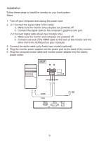
Page 17 highlights
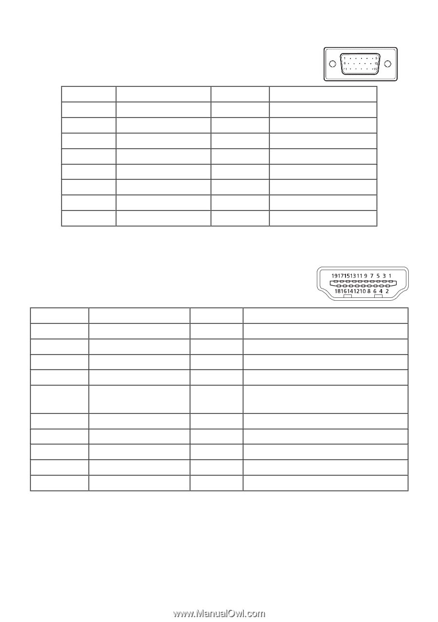
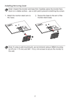
Connector pin assignment 15-pin color display signal cable Threading 1. 2. 3. 4. 5. 6. 7. 8. Explanations Red Green Blue Monitor ground DDC return Red-ground Green-ground Blue-ground Threading Explanations 9. +5 V 10. Logic ground 11. Monitor ground 12. DDC-continuous data 13. Line sync signal 14. Field sync signal 15. DDC-continuous clock 19-pin color display signal cable* Threading 1. 2. 3. 4. Use Threading TMDS data 2 + 10. TMDS data 2 mask 11. TMDS data 2 - 12. TMDS data 1 + 13. 5. TMDS data 1 mask 14. 6. TMDS data 1 - 15. 7. TMDS data 0 + 16. 8. TMDS data 0 mask 17. 9. TMDS data 0 - 18. 19. Use TMDS clock + TMDS clock mask TMDS clock - CEC Reserved (not connected on the device) SCL SDA DDC/CEC ground +5 V power supply Hot plug detection * Limited to specific models 7
-
 1
1 -
2
-
3
-
4
-
5
-
6
-
7
-
8
-
9
-
10
-
11
-
 12
12 -
 13
13 -
 14
14 -
 15
15 -
 16
16 -
 17
17 -
 18
18 -
 19
19 -
 20
20 -
 21
21 -
 22
22 -
23
-
24
-
25
-
26
-
27
-
28
-
29
-
30
 |
 |