Acer EL1210 Service Guide - Page 38
Removing the Side Panel, Screw Quantity, Color, Torque, Part No.
 |
View all Acer EL1210 manuals
Add to My Manuals
Save this manual to your list of manuals |
Page 38 highlights
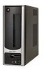
Removing the Side Panel 1. Perform the pre-disassembly procedure described on page 28. 2. Remove the two screws (A) located on the rear edge of the side panel. Screw (Quantity) #6-32 L5 BZN (2) Color Black Torque 5.5 to 6.5 kgf-cm Part No. 86.00J07.B60 3. Slide the side panel toward the back of the chassis until the tabs on the cover disengage with the slots on the chassis. 4. Lift the side panel away from the server and put it aside for reinstallation later. 30 Chapter 3
-
 1
1 -
2
-
3
-
4
-
5
-
6
-
7
-
8
-
9
-
10
-
11
-
12
-
13
-
14
-
15
-
16
-
17
-
18
-
19
-
20
-
21
-
22
-
23
-
24
-
25
-
26
-
27
-
28
-
29
-
30
-
31
-
32
-
 33
33 -
 34
34 -
 35
35 -
 36
36 -
 37
37 -
 38
38 -
 39
39 -
 40
40 -
 41
41 -
 42
42 -
 43
43 -
44
-
45
-
46
-
47
-
48
-
49
-
50
-
51
-
52
-
53
-
54
-
55
-
56
-
57
-
58
-
59
-
60
-
61
-
62
-
63
-
64
-
65
-
66
-
67
-
68
-
69
-
70
-
71
-
72
-
73
-
74
-
75
-
76
-
77
-
78
-
79
-
80
-
81
-
82
-
83
-
84
-
85
-
86
 |
 |

30
Chapter 3
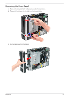
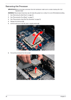
Removing the Side Panel
1.
Perform the pre-disassembly procedure described on page 28.
2.
Remove the two screws (A) located on the rear edge of the side panel.
3.
Slide the side panel toward the back of the chassis until the tabs on the cover disengage with the slots on
the chassis.
4.
Lift the side panel away from the server and put it aside for reinstallation later.
Screw (Quantity)
Color
Torque
Part No.
#6-32 L5 BZN (2)
Black
5.5 to 6.5 kgf-cm
86.00J07.B60