Acer R310-U-P3200 User Guide - Page 34
Checkpoint, Beep Code, Description, Memory to memory disabled - ram
 |
UPC - 750519118634
View all Acer R310-U-P3200 manuals
Add to My Manuals
Save this manual to your list of manuals |
Page 34 highlights
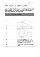
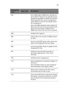
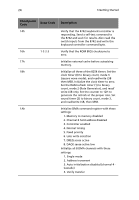
24 3 Getting Started Checkpoint Code Beep Code 14h 16h 1-2-2-3 17h 18h 1Ah Description Verify that the 8742 keyboard controller is responding. Send a self-test command to the 8742 and wait for results. Also read the switch inputs from the 8742 and write the keyboard controller command byte. Verify that the ROM BIOS checksums to zero. Initialize external cache before autosizing memory. Initialize all three of the 8254 timers. Set the clock timer (0) to binary count, mode 3 (square wave mode), and read/write LSB then MSB. Initialize the clock timer to zero. Set the RAM refresh timer (1) to binary count, mode 2 (Rate Generator), and read/ write LSB only. Set the counter to 12H to generate the refresh at the proper rate. Set sound timer (2) to binary count, mode 3, and read/write LSB, then MSB. Initialize DMA command register with these settings: 1. Memory to memory disabled 2. Channel 0 hold address disabled 3. Controller enabled 4. Normal timing 5. Fixed priority 6. Late write selection 7. DREQ sense active 8. DACK sense active low Initialize all 8 DMA channels with these settings: 1. Single mode 2. Address increment 3. Auto initialization disabled (channel 4 Cascade) 4. Verify transfer
-
 1
1 -
2
-
3
-
4
-
5
-
6
-
7
-
8
-
9
-
10
-
11
-
12
-
13
-
14
-
15
-
16
-
17
-
18
-
19
-
20
-
21
-
22
-
23
-
24
-
25
-
26
-
27
-
28
-
 29
29 -
 30
30 -
 31
31 -
 32
32 -
 33
33 -
 34
34 -
 35
35 -
 36
36 -
 37
37 -
 38
38 -
 39
39 -
40
-
41
-
42
-
43
-
44
-
45
-
46
-
47
-
48
-
49
-
50
-
51
-
52
-
53
-
54
-
55
-
56
-
57
-
58
-
59
-
60
-
61
-
62
-
63
-
64
-
65
-
66
-
67
-
68
-
69
-
70
-
71
-
72
-
73
-
74
-
75
-
76
-
77
-
78
-
79
-
80
-
81
-
82
-
83
-
84
-
85
-
86
-
87
-
88
-
89
-
90
-
91
-
92
-
93
-
94
-
95
-
96
-
97
-
98
-
99
-
100
-
101
-
102
-
103
-
104
-
105
-
106
-
107
-
108
-
109
-
110
-
111
-
112
-
113
-
114
-
115
-
116
-
117
-
118
-
119
-
120
-
121
-
122
-
123
-
124
 |
 |
