Acer TravelMate 3300 Service Guide - Page 58
Remove the speaker set from the lower case., Detach the front cover from the lower case.
 |
View all Acer TravelMate 3300 manuals
Add to My Manuals
Save this manual to your list of manuals |
Page 58 highlights
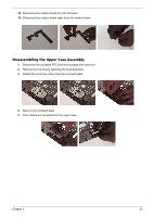
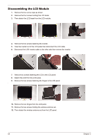
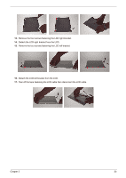
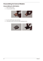
5. Disconnect the microphone cablem from the IO board then detach the microphone. 6. Disconnect the Lid switch cable from the IO board as shown. 7. Remove the four screws fastening the mian board to the lower case. 8. Remove two screws fastening the IO board and one screw holding the modem board. 9. Detach the IO board from the lower case (The IO board is with modem board). 10. Remove the three screws fastening the system fan. 11. Remove the system fan from the lower case. 12. Remove the two screws that fasten the speaker set. 13. Detach the front cover from the lower case. 14. Remove the speaker set from the lower case. 15. Remove the four screws fastening the heatsink to the main board. 16. Detach the heatsink from the main board. 17. Remove the screw that fastens the modem board to the IO board. 52 Chapter 3
-
 1
1 -
2
-
3
-
4
-
5
-
6
-
7
-
8
-
9
-
10
-
11
-
12
-
13
-
14
-
15
-
16
-
17
-
18
-
19
-
20
-
21
-
22
-
23
-
24
-
25
-
26
-
27
-
28
-
29
-
30
-
31
-
32
-
33
-
34
-
35
-
36
-
37
-
38
-
39
-
40
-
41
-
42
-
43
-
44
-
45
-
46
-
47
-
48
-
49
-
50
-
51
-
52
-
 53
53 -
 54
54 -
 55
55 -
 56
56 -
 57
57 -
 58
58 -
 59
59 -
 60
60 -
 61
61 -
 62
62 -
 63
63 -
64
-
65
-
66
-
67
-
68
-
69
-
70
-
71
-
72
-
73
-
74
-
75
-
76
-
77
-
78
-
79
-
80
-
81
-
82
-
83
-
84
-
85
-
86
-
87
-
88
-
89
-
90
-
91
-
92
-
93
-
94
-
95
-
96
-
97
-
98
-
99
-
100
 |
 |
