Adaptec 1542B User Manual - Page 3
AHA-154X
 |
View all Adaptec 1542B manuals
Add to My Manuals
Save this manual to your list of manuals |
Page 3 highlights
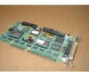
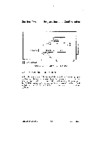
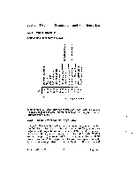
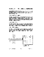
Section Two Preparation and Configuration Pin I MICROCODE IIIIIIIMINI J8 J9 Pin 1 BIOS = AHA-15408 Default FIGURE 2-1. JUMPER LOCATIONS 2.3 JUMPER CONFIGURATION All of the jumpers have been preset at the factory to ensure proper system operation with the majority of AT bus systems. This information is provided to help the OEM or system integrator configure the system properly if other option boards present conflicts or if more than one AHA-154X board will be installed in the same system. AHA-1540B/1542B 2-2 adaptec
-
 1
1 -
 2
2 -
 3
3 -
 4
4 -
 5
5 -
 6
6 -
 7
7 -
 8
8 -
 9
9 -
10
-
11
-
12
-
13
-
14
-
15
 |
 |

Section
Two
Preparation
and
Configuration
Pin
I
MICROCODE
IIIIIIIMINI
Pin
1
J8
J9
BIOS
=
AHA-15408
Default
FIGURE
2-1.
JUMPER
LOCATIONS
2.3
JUMPER
CONFIGURATION
All
of
the
jumpers
have
been
preset
at
the
factory
to
ensure
proper
system
operation
with
the
majority
of
AT
bus
systems.
This
infor-
mation
is
provided
to
help
the OEM
or
system
integrator
configure
the
system
properly
if
other
option
boards
present
conflicts
or
if
more
than
one
AHA-154X
board
will
be
installed
in the
same
system.
AHA-1540B/1542B
2-2
adaptec