Adaptec 1542B User Manual - Page 8
AHA-1540B/1542B.
 |
View all Adaptec 1542B manuals
Add to My Manuals
Save this manual to your list of manuals |
Page 8 highlights
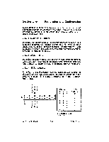
Section Two Preparation and Configuration 2.3.1.6 AT Interrupt Channel There are two jumper blocks involved in selecting the AT interrupt channel. These are J5 and J9. The AT interrupt channel jumpers consist of pin pairs 9, 10, and 11 in the large block of jumper pin pairs J5. The interrupt channel reported to the AT during the Return Configuration Command is set by these jumpers according to the following table. The default is interrupt channel 11. Jumper set J9 selects the AT interrupt channel to be used by the AHA-1540B/1542B. This jumper set is located near the bottom center of the host adapter. Pin pair 1 is the leftmost pair of pins. The interrupt channel used is set according to the following table. The default interrupt channel is 11. Interrupt Channel Select bit 0 Interrupt Channel Select bit 1 Interrupt Channel Select bit 2 J5 INTERRUPT CHANNELS PIN-PAIR 9 10 11 00 0 x0 0 0x 0 xx 0 00 x x0 x INTERRUPT CHANNEL 9 10 11* 12 14 15 0 0 0 0 0 0 0 0 0 x 0 0 0 J5 0 0 0 0 0 0 0 0 0 x 0 0 0 rn cs, a- al as a a0 tr. b: x = Jumper Installed * = Default AHA-1540B/1542B 2-7 adaptec
-
 1
1 -
2
-
 3
3 -
 4
4 -
 5
5 -
 6
6 -
 7
7 -
 8
8 -
 9
9 -
 10
10 -
 11
11 -
 12
12 -
 13
13 -
14
-
15
 |
 |
