Adaptec 2221000 Quick Installation Guide - Page 8
Step 3: Setting the Drive Slot and Enclosure IDs, Step 4: Connecting the I/O Cables - specifications
 |
UPC - 760884149805
View all Adaptec 2221000 manuals
Add to My Manuals
Save this manual to your list of manuals |
Page 8 highlights
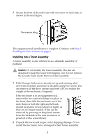
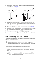
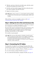
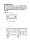
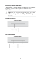
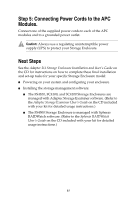
2 With the cam lever of the drive slot fully open, slide the carrier into the slot until the lever starts to close. 3 Push the cam lever until it engages the latch on the left side of the carrier assembly and clicks into place. 4 Repeat for all drive carriers. Note: Either a drive carrier or a carrier blank must be installed in all the slots of the enclosure to maintain proper airflow and cooling. When all drive carriers are installed, continue with Step 5: Connecting Power Cords to the APC Modules. Step 3: Setting the Drive Slot and Enclosure IDs Each drive slot has a unique ID assigned to it. The IDs are assigned by a combination of enclosure ID and slot number. Enclosure IDs must be assigned before the unit is powered on. You set the enclosure ID to any number on the ID switch of the ES module. The ES module is located on the rear of the Storage Enclosure, between the two APC modules. Slot numbers are preassigned. Note: The enclosure ID numbers available on the ID switch vary by enclosure model, and are not available on the SC4100. For detailed information about your specific Storage Enclosure, refer to the Adaptec 2U Storage Enclosure Installation and User's Guide on the CD. Step 4: Connecting the I/O Cables To connect the I/O cables to your Storage Enclosure, follow the instructions provided for your specific Storage Enclosure interface: ■ For a SATA interface (Adaptec FS4100 or FS4500), see page 8. ■ For an FC interface (Adaptec FC4100), see page 9. ■ For an Ultra320 SCSI interface (Adaptec SC4100), see page 10. 7
-
 1
1 -
2
-
 3
3 -
 4
4 -
 5
5 -
 6
6 -
 7
7 -
 8
8 -
 9
9 -
 10
10 -
 11
11 -
 12
12 -
 13
13
 |
 |