Alesis DM10 X Kit Mesh Operation Manual - Page 10
Rear Panel Features, Power Switch, Power In, Main Out, Aux Out, Aux In, Midi In, Midi Out
 |
View all Alesis DM10 X Kit Mesh manuals
Add to My Manuals
Save this manual to your list of manuals |
Page 10 highlights
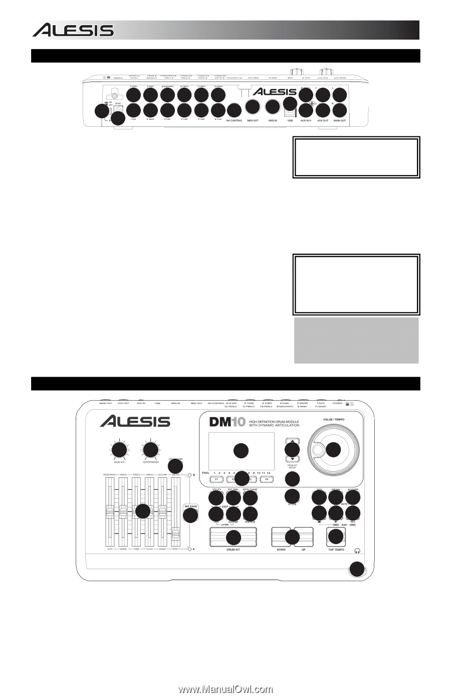
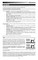
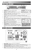
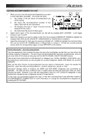
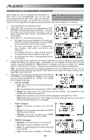
REAR PANEL FEATURES 999999 543 129 9 9 9 9 99 8 7 65 4 3 1. POWER SWITCH - Turns the module on and off. 2. POWER IN - Connect the included AC adapter to this input, then connect the adapter to a power source. 3. MAIN OUT - Use 1/4" TS cables to connect these outputs to an amplifier or speaker system. The volume of these outputs is controlled by the MAIN VOL knob on the top panel. WARNING: Use only the included Alesis power supply with the DM10 module. 4. AUX OUT - Use a 1/4" TS cables to connect these outputs to a monitor system or recording device. The AUX OUT signal can be set to be identical to or independent of the MAIN OUT signal. 5. AUX IN - Connect an external sound source, such as a CD player, to these inputs using a stereo pair of RCA cables. 6. USB - Use a standard USB cable (included) to connect the module to your computer via this USB port. This connection allows the module to send MIDI messages via USB to an external drum software module. You can also IMPORTANT: Always turn transmit SysEx files over this connection. down your volume level(s) to 7. MIDI IN - Use a standard five-pin MIDI cable to connect this zero before plugging or input to the MIDI OUT of an external MIDI device. unplugging your cables from 8. MIDI OUT - Use a standard five-pin MIDI cable to connect this your triggers or the module. output to the MIDI IN of an external MIDI device. 9. TRIGGER INPUTS - Connect the triggers of your drum kit to the Note: The module's HI-HAT appropriate inputs here. Please note that dual-zone pads or CONTROL TRIGGER INPUT cymbals (e.g., a drum with head and rim triggers or a cymbal with does not support keyboard-style bow and bell sounds) will require TRS cables to trigger both expression pedals. zones. TOP PANEL FEATURES 12 7 6 8 14 15 16 4 5 17 18 19 13 9 10 12 20 21 22 23 24 25 26 11 27 3 1. MAIN VOLUME - Adjusts the volume level of the MAIN OUT. 2. HEADPHONES VOLUME - Adjusts the volume level of the HEADPHONES OUTPUT on the module's front panel. The HEADPHONES VOLUME is independent of the module's MAIN VOLUME. 3. HEADPHONES OUTPUT - Connect your 1/4" headphones to this output. You can adjust the volume of this output with the HEADPHONES volume knob on the module's top panel. 4. MIXER - Slide these faders to adjust the levels for the different groups of drum sounds. Each fader controls a drum sound in each bank. The current bank (A or B) is determined by the MIX BANK button. 6
-
 1
1 -
2
-
3
-
4
-
 5
5 -
 6
6 -
 7
7 -
 8
8 -
 9
9 -
 10
10 -
 11
11 -
 12
12 -
 13
13 -
 14
14 -
 15
15 -
16
-
17
-
18
-
19
-
20
-
21
-
22
-
23
-
24
-
25
-
26
-
27
-
28
-
29
-
30
-
31
-
32
-
33
-
34
-
35
-
36
-
37
-
38
-
39
-
40
-
41
-
42
-
43
-
44
-
45
-
46
-
47
-
48
-
49
-
50
-
51
-
52
 |
 |