Alesis RA500 User Manual - Page 35
Architect's and Engineer's Specifications
 |
View all Alesis RA500 manuals
Add to My Manuals
Save this manual to your list of manuals |
Page 35 highlights
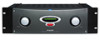
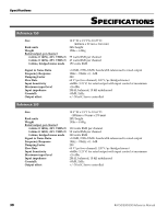
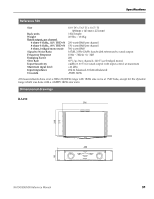
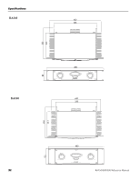
Architect's and Engineer's Specifications The power amplifier shall be a two-channel unit capable of being switched to single-channel bridged mode operation. All components shall be of high quality and mechanical construction and optimized for high reliability under adverse physical and electrical conditions. Cooling shall be convection-type only, with no fan mounted inside the amplifier. The inputs shall be differentially balanced with active current sources for rejection of electromagnetic interference. The input connectors shall be 3-conductor 1/4" TRS jacks mounted on the back panel. Additional unbalanced RCA/ phono inputs shall also be mounted on the back panel. [RA300 and RA500: There shall also be provision for female XLR input jacks on each channel.] The output stages of the amplifier shall be a high current, triple darlington type biased for class AB operation, fully rated for continuous 4 ohm operation with 2 ohm dynamic stability (stereo mode only). An active DC servo circuit is to be employed to automatically null DC output voltage offsets. The amplifier shall feature active circuitry that continuously monitors the output stage for excessive DC offset, short circuits and thermal overload. In the event of an output fault, the protection circuitry will activate the output relay and disconnect the loudspeaker load. This circuitry will also mute the amplifier during power on/off transitions. The power supplies of the amplifier shall utilize heavy-duty stacked steel EI laminated transformers for maximum performance and reliability, with high current bridge rectifiers, massive secondary capacitors and current in-rush limiters. An external voltage selection switch on the back panel shall allow the user to switch between 120-volt and 230volt AC power input. A power switch shall be provided on the front panel with an on/off indicator lamp. The front panel of the amplifier shall feature two detented volume controls capable of delivering full rated power at full clockwise rotation with a +4 dBu input, and turning the amplifier down at least 70 dB or to silence at full counterclockwise rotation. RA150/300/500 Reference Manual Specifications The chassis shall be rack mountable in a standard 19" EIA equipment rack. Output connectors shall be two-way binding posts capable of accepting heavy gauge wire or banana-type connectors. The power output of the amplifier shall be 75 watts per channel (RA150), 150 watts per channel (RA300) or 250 watts per channel (RA500) into a 4-ohm load, with no more than .02% total harmonic distortion. The units shall be capable of 150 watts (RA150), 300 watts (RA300), or 500 watts (RA500) into an 8-ohm load when operated in bridged mono mode with no more than .05% total harmonic distortion. The amplifier shall be an Alesis RA150/300/500 Reference Series power amplifier. 33
-
 1
1 -
2
-
3
-
4
-
5
-
6
-
7
-
8
-
9
-
10
-
11
-
12
-
13
-
14
-
15
-
16
-
17
-
18
-
19
-
20
-
21
-
22
-
23
-
24
-
25
-
26
-
27
-
28
-
29
-
 30
30 -
 31
31 -
 32
32 -
 33
33 -
 34
34 -
 35
35 -
 36
36 -
 37
37 -
 38
38
 |
 |