Ariens Compact 24 Owners Manual - Page 10
Install Remote Deflector Cable, Remote Deflector Control
 |
View all Ariens Compact 24 manuals
Add to My Manuals
Save this manual to your list of manuals |
Page 10 highlights
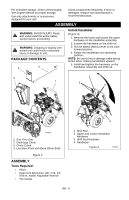
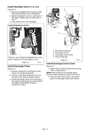
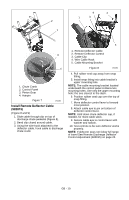
. 4 2 1 3 2 1 3 4 1. Chute Crank 2. Control Panel 3. Pinion Gear 4. Hairpin Figure 7 OS8060 Install Remote Deflector Cable (920015) (Figure 8 and 9) 1. Slide cable through clip on top of discharge chute pedestal (Figure 8). 2. Bend clip closed around cable. 3. Using the wire hook attached to the deflector cable, hook cable to discharge chute crank. 5 1. Remote Deflector Cable 2. Remote Deflector Control 3. Cable Clip 4. Wire Cable Hook 5. Cable Mounting Bracket Figure 8 OS8064 4. Pull rubber seal cap away from snap fitting. 5. Install snap fitting into cable bracket's upper mounting hole. NOTE: The cable mounting bracket located underneath the control panel contains two mounting holes. Use only the upper mounting hole; the one closest to the dash. 6. Position rubber seal cap over the top of snap fitting. 7. Move deflector control lever to forward most position. 8. Attach cable eye to pin on bottom of deflector control lever. NOTE: Hold down chute deflector cap, if needed, for more cable slack. 9. Secure cable eye to control lever with washer and hairpin. 10. Test controls to be sure deflector works properly. NOTE: If deflector does not follow full range of travel See Remote Discharge Deflector Control Adjustment (920015) on page 23. GB - 10
-
 1
1 -
2
-
3
-
4
-
 5
5 -
 6
6 -
 7
7 -
 8
8 -
 9
9 -
 10
10 -
 11
11 -
 12
12 -
 13
13 -
 14
14 -
 15
15 -
16
-
17
-
18
-
19
-
20
-
21
-
22
-
23
-
24
-
25
-
26
-
27
-
28
-
29
-
30
-
31
-
32
-
33
-
34
-
35
-
36
-
37
-
38
 |
 |
