Ariens Compact 24 Owners Manual - Page 11
Check Function of all Controls - in
 |
View all Ariens Compact 24 manuals
Add to My Manuals
Save this manual to your list of manuals |
Page 11 highlights
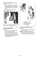
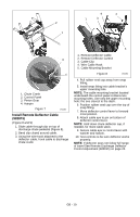
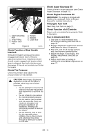
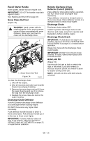
. 2 1 5 6 4 3 1. Upper Mounting Hole 2. Snap Fitting 3. Rubber Seal Cap 4. Hairpin 5. Washer 6. Cable Eye Figure 9 OS8066 Check Function of Dual Handle Interlock Without the engine running, press down (engage) both clutch levers. Release attachment clutch lever. Attachment clutch should remain engaged until traction clutch lever is released, then both clutches must disengage. If they do not, contact your Dealer for repairs. Check Tire Pressure Check tire pressure and adjust to the pressure listed on tire sidewall. Check Auger Gearcase Oil Check oil level in auger gearcase (see Check Auger Gearcase on page 21). Check Engine Crankcase Oil IMPORTANT: The engine is shipped with 5W-30 oil in crankcase. Refer to Engine Manual for detailed instructions. Fill Engine Fuel Tank See Filling Fuel Tank on page 17. Check Function of all Controls Ensure unit runs and performs properly. Refer to Operation. Run-in Attachment Belt 1. Start unit in a well-ventilated area according to Starting and Shut Off on page 18. 2. Engage attachment clutch lever and run attachment for about 15 minutes. 3. Stop unit, wait for all moving parts to stop, and remove spark plug wire. 4. Adjust belt finger, if necessary. See Replace Attachment Drive Belt on page 25. 5. Adjust clutch idler according to Attachment Clutch/Brake Adjustment on page 27. CAUTION: Avoid injury! Explosive separation of tire and rim parts is possible when they are serviced incorrectly: • Do not attempt to mount a tire without the proper equipment and experience to perform the job. • Do not inflate the tires above the recommended pressure. • Do not weld or heat a wheel and tire assembly. Heat can cause an increase in air pressure resulting in an explosion. Welding can structurally weaken or deform the wheel. • Do not stand in front or over the tire assembly when inflating. Use a clip-on chuck and extension hose long enough to allow you to stand to one side. GB - 11
-
 1
1 -
2
-
3
-
4
-
5
-
 6
6 -
 7
7 -
 8
8 -
 9
9 -
 10
10 -
 11
11 -
 12
12 -
 13
13 -
 14
14 -
 15
15 -
 16
16 -
17
-
18
-
19
-
20
-
21
-
22
-
23
-
24
-
25
-
26
-
27
-
28
-
29
-
30
-
31
-
32
-
33
-
34
-
35
-
36
-
37
-
38
 |
 |
