Ariens Compact 24 Owners Manual - Page 30
FRICTION DISC REPLACEMENT, Remove Friction Disc - washer
 |
View all Ariens Compact 24 manuals
Add to My Manuals
Save this manual to your list of manuals |
Page 30 highlights
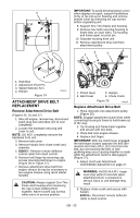
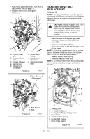
Traction Clutch Lever 7-1/2 - 8 in.(19.0 - 20.3 cm) 1 2 Figure 36 OS8270 To adjust traction clutch (Figure 37): 1. With the traction drive clutch lever disengaged, loosen the jam nut on the cable adjuster. Turn adjustment barrel up the cable to decrease the distance between clutch lever and handlebar. Turn the adjustment barrel down the cable to increase the distance between clutch lever and handlebar. 2. Check traction clutch lever distance and repeat adjustment steps if necessary. 3. Tighten jam nut on traction cable adjustment barrel. 4. With the clutch disengaged, check that there is more than 1/32 in. (0.8 mm) clearance between friction disc and drive plate assembly (Figure 38) on page 31. 3 5 4 6 1. Traction Drive Clutch Cable 2. Adjustment Barrel 3. Jam Nut 4. Adjustment Pivot Pin 5. Speed Selector Arm 6. Attachment Clutch Arm Figure 37 OS8275 FRICTION DISC REPLACEMENT Remove Friction Disc (Figure 38): 1. Shut off engine, remove key, disconnect spark plug wire and allow unit to cool completely. CAUTION: Before tipping unit, remove enough fuel so that no spills occur. 2. Place the unit into the service position on a level surface. 3. Remove lockpins from wheel axles and remove wheels. 4. Remove bottom cover by removing six hex bolts. 5. Disconnect pivot pin from the speed selector arm. Save the hardware for reinstallation. 6. Remove spring hairpin nearest drive gear from hex shaft. 7. Remove left bearing flange from frame. 8. Slide hex shaft to the left to remove the flat washer, pinion gear and friction disc assembly from the hex shaft. NOTE: Be sure to save washers between bearing and sliding fork for reassembly. 9. Remove friction disc assembly from frame. GB - 30
-
 1
1 -
2
-
3
-
4
-
5
-
6
-
7
-
8
-
9
-
10
-
11
-
12
-
13
-
14
-
15
-
16
-
17
-
18
-
19
-
20
-
21
-
22
-
23
-
24
-
 25
25 -
 26
26 -
 27
27 -
 28
28 -
 29
29 -
 30
30 -
 31
31 -
 32
32 -
 33
33 -
 34
34 -
 35
35 -
36
-
37
-
38
 |
 |
