Ariens Compact Track 24 Owners Manual - Page 11
INSTALL DISCHARGE CHUTE, AND DISCHARGE CHUTE CRANK, Oval Head Machine Screw
 |
View all Ariens Compact Track 24 manuals
Add to My Manuals
Save this manual to your list of manuals |
Page 11 highlights
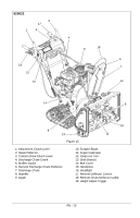
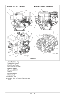
2 2 3 1 4 1 3 1. Trigger Cable Assembly 2. Oval Head Machine Screw 3. Internal Locking Washer Figure 9 INSTALL DISCHARGE CHUTE AND DISCHARGE CHUTE CRANK (Figures 10 and 11) 1. Grease underside of discharge chute ring (if not already greased). 2. Remove mounting hardware from auger housing. 3. Install discharge chute over opening in the auger housing. Finger tighten the mounting hardware removed in step 2. NOTICE: Leave discharge chute pedestal loose to help install the chute crank. 1. Mounting Holes 5 2. Discharge Chute 3. Discharge Chute Ring 4. Chute Pedestal 5. Mounting Hardware Figure 10 4. Remove gear cover from top of chute pedestal. 5. Slide Chute Crank through the nylon bushing in the support bracket under control panel. NOTICE: Be careful not to damage nylon bushing when attaching crank to the control panel. 6. Connect the chute crank to the pinion gear on discharge chute with spring clip pin. 7. Replace gear cover on top of chute pedestal. 8. Orient the chute and pedestal to its most vertical position and tighten pedestal hardware to 14.8 - 31.0 lbf-ft (20 - 42 N•m). EN - 11
-
 1
1 -
2
-
3
-
4
-
5
-
 6
6 -
 7
7 -
 8
8 -
 9
9 -
 10
10 -
 11
11 -
 12
12 -
 13
13 -
 14
14 -
 15
15 -
 16
16 -
17
-
18
-
19
-
20
-
21
-
22
-
23
-
24
-
25
-
26
-
27
-
28
-
29
-
30
-
31
-
32
-
33
-
34
-
35
-
36
-
37
-
38
-
39
-
40
-
41
-
42
-
43
-
44
-
45
-
46
 |
 |
