Ariens Hydro Pro 32 Owners Manual - Page 25
Discharge Chute Control, Speed Selector, Adjustment, Attachment Clutch/brake
 |
View all Ariens Hydro Pro 32 manuals
Add to My Manuals
Save this manual to your list of manuals |
Page 25 highlights
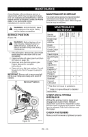
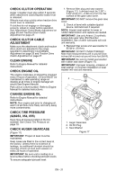
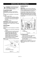
DISCHARGE CHUTE CONTROL (Figure 23) If chute does not stay in position while throwing snow or if chute does not rotate freely, adjust the cable under the gear cover so the chute lock fingers engage or disengage the locking gear. If chute does not stay in position: Loosen the cable by loosening the rear adjustment nut, and then tightening the forward adjustment nut against the bracket until the lock arm engages the gear teeth. Forward Adjustment Nut Rearward Adjustment Nut Figure 23 If chute does not rotate freely: Tighten the cable by loosening the forward adjustment nut, and then tightening the rear adjustment nut against the bracket until all cable slack is removed (Figure 23). SPEED SELECTOR ADJUSTMENT (Figure 24) To set neutral position: 1. Place machine on blocks, with the wheels/tracks off of the ground. 2. Disconnect the trunion pin from the bell crank. 3. Start the engine. 4. Hold down the traction clutch paddle. 5. Move bell crank to the position where the wheels/tracks are not moving. 6. Shut off engine. 7. Move speed control to the neutral position and hold in place. 8. Adjust trunion pin to a position where it can be re-inserted into the bell crank hole. Without moving the bell crank, reinstall the trunion pin. 9. Remove blocks from under machine. 1 3 4 5 1. Shift Rod 2. Trunnion Pin 3. Bell Crank 4. Hairpin 5. Bell Crank Hole Figure 24 2 OS7185 ATTACHMENT CLUTCH/BRAKE ADJUSTMENT IMPORTANT: IMPROPER ADJUSTMENT could result in unexpected movement of auger and impeller causing death or serious injury. Auger/Impeller must stop within 5 seconds when Attachment Clutch/Impeller Brake lever is released. Remove Attachment Cable Slack (Figure 25 and 26) 1. Shut off engine, remove key, disconnect spark plug wire and allow unit to cool completely. 2. Loosen hardware securing belt cover to unit. NOTE: DO NOT completely remove the hardware from unit. 3. Remove belt cover. 4. Loosen jam nut on cable adjustment barrel, and then turn the adjustment barrel up or down to lengthen or shorten cable and remove all cable slack (Figure 25). EN - 25
-
 1
1 -
2
-
3
-
4
-
5
-
6
-
7
-
8
-
9
-
10
-
11
-
12
-
13
-
14
-
15
-
16
-
17
-
18
-
19
-
 20
20 -
 21
21 -
 22
22 -
 23
23 -
 24
24 -
 25
25 -
 26
26 -
 27
27 -
 28
28 -
 29
29 -
 30
30 -
31
-
32
-
33
-
34
-
35
-
36
-
37
-
38
 |
 |
