Ariens Hydro Pro 32 Owners Manual - Page 27
Traction Drive Clutch, Adjustment, Attachment Drive Belts, Replacement, Check Attachment Brake
 |
View all Ariens Hydro Pro 32 manuals
Add to My Manuals
Save this manual to your list of manuals |
Page 27 highlights
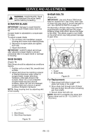
Check Attachment Brake (Figure 28) 1. With the clutch lever disengaged, brake pad must contact attachment belts. With clutch lever engaged, brake pad must be more than 1/16" (1.6 mm) from belts. If there is more than 1/16" (1.6 mm) gap, go to Check Belt Finger Clearance on page 27. If there is less than 1/16" (1.6 mm) gap, go to step 2. 2 Check belt finger clearance here. With the attachment clutch engaged, there should be less than 1/8" (3 mm) clearance between the belts and the belt finger. The belt finger should not touch the belts. 1 1 2 Minimum of 1/16" (1.6 mm). 1. Brake Shoe and Pad 2. Attachment Pulley Figure 28 OS7201 2. If there is less than 1/16" (1.6 mm) gap between brake pad and belt, loosen idler adjustment nut, and move idler away from belt. 3. Position idler to achieve a 1/16" (1.6 mm) minimum brake pad gap and a 1/2 - 7/8" (12.7 - 22.2 mm) gap between the plastic roller and the frame. IMPORTANT: If adjustments cannot be brought into specified ranges see your Dealer for repairs. Check Belt Finger Clearance (Figure 29) 1. With clutch lever engaged, the belt finger located opposite the belt idler must be less than 1/8" (3 mm) from belts, but not touching the belts. To adjust belt finger, loosen the bolts and move the finger to the proper position. Tighten the bolts and recheck the belt finger clearance. 2. Replace the belt cover and tighten hardware. 1 1. Mounting Hardware 2. Belt Finger Figure 29 TRACTION DRIVE CLUTCH ADJUSTMENT 1. Loosen jam nut on traction cable adjustment barrel. Turn adjustment barrel down to shorten cable and remove all cable slack. ATTACHMENT DRIVE BELTS REPLACEMENT (Figure 30) Remove old attachment drive belts 1. Shut off engine, remove key, disconnect spark plug wire and allow unit to cool completely. 2. Loosen hardware securing belt cover to unit (Figure 30). NOTE: Do NOT completely remove the hardware from unit. 3. Remove belt cover. 4. Remove chute gear cover. 5. Remove hair pin in front of chute gear assembly and slide the discharge chute rod rearward. IMPORTANT: Disconnect chute lock cable and deflector cable. 6. Remove belt finger (Figure 29). IMPORTANT: Use care when rotating the belt fingers. DO NOT bend belt fingers out of shape. EN - 27
-
 1
1 -
2
-
3
-
4
-
5
-
6
-
7
-
8
-
9
-
10
-
11
-
12
-
13
-
14
-
15
-
16
-
17
-
18
-
19
-
20
-
21
-
 22
22 -
 23
23 -
 24
24 -
 25
25 -
 26
26 -
 27
27 -
 28
28 -
 29
29 -
 30
30 -
 31
31 -
 32
32 -
33
-
34
-
35
-
36
-
37
-
38
 |
 |
