Asus A7S8X-MX User manual for A7S8X-MX
Asus A7S8X-MX Manual
 |
View all Asus A7S8X-MX manuals
Add to My Manuals
Save this manual to your list of manuals |
Asus A7S8X-MX manual content summary:
- Asus A7S8X-MX | User manual for A7S8X-MX - Page 1
A7S8X-MX Motherboard - Asus A7S8X-MX | User manual for A7S8X-MX - Page 2
express written permission of ASUSTeK COMPUTER INC. ("ASUS"). Product warranty or service will not be extended if: (1) the ASUS HAS BEEN ADVISED OF THE POSSIBILITY OF SUCH DAMAGES ARISING FROM ANY DEFECT OR ERROR IN THIS MANUAL OR PRODUCT. SPECIFICATIONS AND INFORMATION CONTAINED IN THIS MANUAL - Asus A7S8X-MX | User manual for A7S8X-MX - Page 3
vii About this guide viii Typography ix A7S8X-MX specifications summary x Chapter 1: Product introduction 1.1 Welcome 1-2 1.2 Package contents 1-2 1.3 Special features 1-3 1.3.1 Product highlights 1-3 1.3.2 Innovative ASUS features 1-4 1.4 Before you proceed 1-5 1.5 Motherboard overview - Asus A7S8X-MX | User manual for A7S8X-MX - Page 4
ASUS CrashFree BIOS utility 2-6 2.1.5 ASUS Update utility 2-7 2.2 BIOS Setup program 2-10 2.2.1 BIOS menu bar 2-11 2.2.2 Legend bar 2-11 2.3 Main Menu 2-13 2.3.1 System Time 2-13 2.3.2 System Date 2-13 2.3.3 Legacy Diskette A 2-13 2.3.4 HDD SMART Monitoring 2-13 2.3.5 Installed Memory - Asus A7S8X-MX | User manual for A7S8X-MX - Page 5
Contents Chapter 3: Software support 3.1 Installing an operating system 3-2 3.2 Support CD information 3-2 3.2.1 Running the support CD 3-2 3.2.2 Drivers menu 3-3 3.2.3 Utilities menu 3-4 3.2.4 ASUS Contact information 3-5 v - Asus A7S8X-MX | User manual for A7S8X-MX - Page 6
used in accordance with manufacturer's instructions, may cause harmful interference to radio or television reception, which can be determined by turning the equipment off and on, the user is cables for connection of the monitor to the graphics card is required to assure compliance with FCC - Asus A7S8X-MX | User manual for A7S8X-MX - Page 7
Contact a qualified service technician or your retailer. Operation safety • Before installing the motherboard and adding devices on it, carefully read all the manuals that came with . • If you encounter technical problems with the product, contact a qualified service technician or your retailer. vii - Asus A7S8X-MX | User manual for A7S8X-MX - Page 8
the BIOS parameters are also provided. • Chapter 3: Software support This chapter describes the contents of the support CD that comes with the motherboard package. Where to find more information Refer to the following sources for additional information and for product and software updates. 1. ASUS - Asus A7S8X-MX | User manual for A7S8X-MX - Page 9
following symbols used throughout this manual. D A N G E R / W A R N I N G : Information to prevent injury to yourself when trying to complete a task. C A U T I O N : Information to prevent damage to the components when trying to complete a task. I M P O R T A N T : Instructions that you MUST follow - Asus A7S8X-MX | User manual for A7S8X-MX - Page 10
A7S8X-MX specifications summary CPU Chipset Front Side Bus Memory Expansion slots Storage Audio LAN USB Special features BIOS features Rear panel Socket A for AMD Athlon™ XP/Sempron™ processors Northbridge: SiS 741GX Southbridge: SiS 964 (without RAID support) 333/266/200 MHz 2 x 184-pin DIMM - Asus A7S8X-MX | User manual for A7S8X-MX - Page 11
1 x System panel connector I n d ustry standard PCI 2.2, USB 2.0 Support CD contents Device drivers ASUS PC Probe ASUS Update Anti-virus software (OEM version) Form Factor Micro ATX form factor: 9.6 in x 7.8 in (24.4 cm x 19.8 cm) *Specifications are subject to change without notice. xi - Asus A7S8X-MX | User manual for A7S8X-MX - Page 12
xii - Asus A7S8X-MX | User manual for A7S8X-MX - Page 13
This chapter describes the motherboard features and the new technologies it supports. 1Product introduction ASUS A7S8X-MX 1-1 - Asus A7S8X-MX | User manual for A7S8X-MX - Page 14
Package contents Check your motherboard package for the following items. Motherboard Cables Accessory Application CD Documentation ASUS A7S8X-MX motherboard 1 x Serial port (COM) cable 1 x Ultra DMA cable 1 x Floppy disk drive cable I/O shield ASUS motherboard support CD User guide If any of the - Asus A7S8X-MX | User manual for A7S8X-MX - Page 15
™ XP/Sempron™ processors. With an integrated low-latency high-bandwidth memory controller, the motherboard allows increased office productivity and enhanced digital media experience. See page 1-8. AGP 8X support The AGP 8X (AGP 3.0) VGA interface specification enables enhanced graphics performance - Asus A7S8X-MX | User manual for A7S8X-MX - Page 16
® Athlon XP™ installed, the motherboard offers automatic CPU Overheating Protection to prolong the life of the entire system. If the CPU temperature exceeds the set criteria, the PC shuts down automatically. ASUS EZ Flash BIOS With the ASUS EZ Flash, you can easily update the system BIOS even before - Asus A7S8X-MX | User manual for A7S8X-MX - Page 17
This is a reminder that you should shut down the system and unplug the power cable before removing or plugging in any motherboard component. The illustration below shows the location of the onboard LED. A7S8X-MX ® A7S8X-MX Onboard LED SB_PWR1 ON Standby Power OFF Powered Off ASUS A7S8X-MX 1-5 - Asus A7S8X-MX | User manual for A7S8X-MX - Page 18
the image below. 1.5.2 Screw holes Place six (6) screws into the holes indicated by circles to secure the motherboard to the chassis. Do not overtighten the screws! Doing so can damage the motherboard. Place this side towards the rear of the chassis ® A7S8X-MX 1-6 Chapter 1: Product introduction - Asus A7S8X-MX | User manual for A7S8X-MX - Page 19
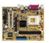
Motherboard layout 19.8cm (7.8in) PS/2KBMS T: Mouse B: Keyboard CPU_FAN1 SPDIF_O Socket 462 DDR DIMM1 (64/72 bit, 184-pin module) DDR DIMM2 (64/72 bit, 184-pin module) ATXPWR PARALLEL PORT VGA1 USBPW1234 A7S8X-MX CLRTC1 PANEL1 24.4cm (9.6in) SB_PWR1 SATA1 SATA2 ASUS A7S8X-MX 1-7 - Asus A7S8X-MX | User manual for A7S8X-MX - Page 20
with core speeds of less than 1 GHz on this motherboard. Installing the CPU Follow these steps to install a CPU. 1. Locate the 462-pin ZIF socket on the motherboard. CPU NOTCH TO INNER CORNER A7S8X-MX ® A7S8X-MX CPU Socket 462 AMD™ CPU LOCK LEVER CPU NOTCH 1-8 Chapter 1: Product introduction - Asus A7S8X-MX | User manual for A7S8X-MX - Page 21
The CPU fits only in one correct orientation. DO NOT force the CPU into the socket to prevent bending the pins and damaging the CPU! 5. When the CPU is in place, push down the socket lever to secure the CPU. The lever clicks on the side tab to indicate that it is locked. ASUS A7S8X-MX 1-9 - Asus A7S8X-MX | User manual for A7S8X-MX - Page 22
A7S8X-MX DIMM1 DIMM2 80 Pins 104 Pins 1.7 System memory 1.7.1 Overview The motherboard comes with two Double Data Rate (DDR) Dual Inline Memory Module (DIMM) sockets. These sockets support up to 2 GB system memory using 184-pin PC2700/PC2100 unbuffered DDR DIMMs and allow up to 2.7 GB/s data - Asus A7S8X-MX | User manual for A7S8X-MX - Page 23
DIMM_A2 Populated - Populated - Populated Populated Memory frequency/CPU FSB synchronization CPU FSB 333 MHz 266 MHz DDR DIMM Type PC2700/PC2100 PC2100 Memory Frequency 333/266 MHz 266 MHz Obtain DDR DIMMs only from qualified vendors for better system performance. ASUS A7S8X-MX 1-11 - Asus A7S8X-MX | User manual for A7S8X-MX - Page 24
components. Failure to do so may cause severe damage to both the motherboard and the components. 1. Unlock a DIMM socket by pressing the retaining clips retaining clips outward to unlock the DIMM. 1 1 DDR DIMM notch Support the DIMM lightly with your fingers when pressing the retaining clips. The - Asus A7S8X-MX | User manual for A7S8X-MX - Page 25
they support. (if your motherboard is already Turn on the system and change the necessary BIOS settings, if any. See Chapter 2 for information on BIOS setup. 2. Assign an IRQ to the card. Refer to the tables on the next page. 3. Install the software drivers for the expansion card. ASUS A7S8X-MX - Asus A7S8X-MX | User manual for A7S8X-MX - Page 26
2 Programmable Interrupt 4* Communications Port (COM1) 5* Sound Card (sometimes LPT2) 6 Floppy Disk Controller 7* motherboard AGP slot PCI slot 1 PCI slot 2 A B C D used - - - - used - - - - used - When using PCI cards on shared slots, ensure that the drivers support - Asus A7S8X-MX | User manual for A7S8X-MX - Page 27
, make sure that you ask for one with +1.5V specification. Note the notches on the card golden fingers to ensure that they fit the AGP slot on your motherboard. ® Keyed for 1.5v A7S8X-MX Accelerated Graphics Port (AGP1) Install only 1.5V AGP cards on this motherboard! A7S8X-MX ASUS A7S8X-MX 1-15 - Asus A7S8X-MX | User manual for A7S8X-MX - Page 28
Plug the power cord and turn ON the computer. 6. Hold down the key during the boot process and enter BIOS setup to re-enter data. Except when clearing the RTC RAM, never remove the cap on CLRTC jumper default position. Removing the cap will cause system boot failure! A7S8X-MX CLRTC1 12 23 - Asus A7S8X-MX | User manual for A7S8X-MX - Page 29
connected USB devices. Set to +5VSB to wake up from S3 and S4 sleep modes (no power to CPU, DRAM in slow refresh, power supply in reduced power mode). The USBPW1234 jumper is for the rear USB the power supply capability (+5VSB) whether under normal condition or in sleep mode. ASUS A7S8X-MX 1-17 - Asus A7S8X-MX | User manual for A7S8X-MX - Page 30
allow you to set the CPU Front Side Bus (FSB) frequency. Refer to the jumper settings below. 1 FSB_SEL1 FSB_SEL0 100MHZ A7S8X-MX 1 FSB_SEL1 FSB_SEL0 133MHZ 1 ® FSB_SEL1 FSB_SEL0 A7S8X-MX External frequency selection 166MHZ (Default) Make sure you load the BIOS setup default after changing - Asus A7S8X-MX | User manual for A7S8X-MX - Page 31
of the audio ports in 2, 4, or 6-channel configuration. Audio 2, 4, or 6-channel configuration Port Headset 2-channel 4-channel Light Blue Lime Pink Line In Line Out Mic In Rear Speaker Out Front Speaker Out Mic In 6-channel Rear Speaker Out Front Speaker Out Bass/Center ASUS A7S8X-MX 1-19 - Asus A7S8X-MX | User manual for A7S8X-MX - Page 32
o G r a p h i c s A d a p t e r p o r t . This 15-pin port is for a VGA monitor or other VGA-compatible devices. 1 0 . C o a x i a l S / P D I F O u t p o r t . This port connects an external audio output device via a coaxial S/PDIF cable. 1 1 . P S / 2 k e y b o a r d p o r t ( p u r p l e ) . This - Asus A7S8X-MX | User manual for A7S8X-MX - Page 33
of the floppy disk drive. Pin 5 on the connector is removed to prevent incorrect cable connection when using an FDD cable with a covered Pin 5. A7S8X-MX FLOPPY1 ® PIN 1 NOTE: Orient the red markings on the floppy ribbon cable to PIN 1. A7S8X-MX Floppy disk drive connector ASUS A7S8X-MX 1-21 - Asus A7S8X-MX | User manual for A7S8X-MX - Page 34
has three connectors: a blue connector for the primary IDE connector on the motherboard, a black connector for an Ultra DMA 133/100/66 IDE slave device IDE cable for Ultra DMA 133/100/66 IDE devices. A7S8X-MX SEC_IDE PRI_IDE ® A7S8X-MX IDE connectors NOTE: Orient the red markings (usually zigzag) - Asus A7S8X-MX | User manual for A7S8X-MX - Page 35
hard disk drives. A7S8X-MX ® A7S8X-MX SATA connectors SATA2 GND RSATA_TXP2 RSATA_TXN2 GND RSATA_RXP2 RSATA_RXN2 GND SATA1 GND RSATA_TXP1 RSATA_TXN1 GND RSATA_RXP1 RSATA_RXN1 GND Important notes on Serial ATA • Install the Windows® 2000 Service Pack 4 or the XP Service Pack1 before using Serial - Asus A7S8X-MX | User manual for A7S8X-MX - Page 36
the fan connectors. Insufficient air flow inside the system may damage the motherboard components. These are not jumpers! DO NOT place jumper caps on the fan connectors. CPU_FAN1 GND +12V Rotation A7S8X-MX ® A7S8X-MX Fan connectors CHA_FAN1 GND +12V Rotation 1-24 Chapter 1: Product introduction - Asus A7S8X-MX | User manual for A7S8X-MX - Page 37
These USB connectors comply with USB 2.0 specification that supports up to 480 Mbps connection speed. A7S8X-MX USB+8V USB_P8USB_P8+ GND NC USB+5V playing or editing audio files. A7S8X-MX +5V J1B2 J1CY GND GND J1CX J1B1 +5V ® A7S8X-MX Game connector GAME ASUS A7S8X-MX MIDI_IN J2B2 J2CY MIDI_OUT - Asus A7S8X-MX | User manual for A7S8X-MX - Page 38
allow you to receive stereo audio input from sound sources such as a CD-ROM, TV tuner, or MPEG card. A7S8X-MX CD(Black) Right Audio Channel Ground Left Audio Channel AUX(White) Right Audio Channel ® Ground Left Audio Channel A7S8X-MX Internal audio connectors 1-26 Chapter 1: Product introduction - Asus A7S8X-MX | User manual for A7S8X-MX - Page 39
panel audio I/O module that supports either AC '97 audio standard. Connect one end of the front panel audio I/O module cable to this connector. FP_AUDIO1 ® A7S8X-MX Front panel audio connector (COM1) is purchased separately. COM1 PIN 1 ® A7S8X-MX Serial port connector A7S8X-MX ASUS A7S8X-MX 1-27 - Asus A7S8X-MX | User manual for A7S8X-MX - Page 40
system power LED. Connect the 3-pin power LED cable from the system chassis to this connector. The LED lights up when you turn on the system power, and blinks when the system is in sleep mode. PWR_LED1 ® A7S8X-MX Power LED connector A7S8X-MX PLED+ PLED+ PLED- 1-28 Chapter 1: Product introduction - Asus A7S8X-MX | User manual for A7S8X-MX - Page 41
depending on the BIOS settings. Pressing the power switch for more than four seconds while the system is ON turns the system OFF. • Reset button (Blue 2-pin RST) This 2-pin connector is for the chassis-mounted reset button for system reboot without turning off the system power. ASUS A7S8X-MX 1-29 - Asus A7S8X-MX | User manual for A7S8X-MX - Page 42
1-30 Chapter 1: Product introduction - Asus A7S8X-MX | User manual for A7S8X-MX - Page 43
This chapter tells how to change the system settings through the BIOS Setup menus. Detailed descriptions of the BIOS parameters are also provided. 2 BIOS setup ASUS A7S8X-MX 2-1 - Asus A7S8X-MX | User manual for A7S8X-MX - Page 44
this motherboard using the ASUS Update utility. 2.1.1 Creating a bootable floppy disk 1. Do either one of the following to create a bootable floppy disk. DOS environment a. Insert a 1.44 MB floppy disk into the drive. b. At the DOS prompt, type format A:/S then press . Windows® XP environment - Asus A7S8X-MX | User manual for A7S8X-MX - Page 45
. e. Press , then follow screen instructions to continue. 2. Copy the original or the latest motherboard BIOS file to the bootable floppy disk. 2.1.2 AwardBIOS Flash Utility The Basic Input/Output System (BIOS) can be updated using the built-in Flash Memory Writer utility or using a bootable - Asus A7S8X-MX | User manual for A7S8X-MX - Page 46
POST to display the following screen. 5. AWDFLASH checks the new BIOS file from the floppy disk. 6. After verification, AWDFLASH flashes the new BIOS file. Do not shut down the computer during the flash process. 7. After the new BIOS file is copied, the computer returns to POST. 2-4 Chapter - Asus A7S8X-MX | User manual for A7S8X-MX - Page 47
the ASUS website (www.asus.com) to download the latest BIOS file for the motherboard and rename the same to A 7 S 8 X - M X . R O M. 2. Save the BIOS file to a floppy disk, then restart the system. 3. Press + during POST to display the following. EZFlash starting BIOS update Checking - Asus A7S8X-MX | User manual for A7S8X-MX - Page 48
ASUS CrashFree BIOS utility The ASUS CrashFree BIOS is an auto recovery tool that allows you to restore the BIOS file when it fails or gets corrupted during the updating process. You can update a corrupted BIOS file using the motherboard support CD or the floppy disk that contains the updated BIOS - Asus A7S8X-MX | User manual for A7S8X-MX - Page 49
you to manage, save, and update the motherboard BIOS in Windows® environment. The ASUS Update utility allows you to: • Save the current BIOS file • Download the latest BIOS file from the Internet • Update the BIOS from an updated BIOS file • Update the BIOS directly from the Internet, and • View - Asus A7S8X-MX | User manual for A7S8X-MX - Page 50
Updating the BIOS through the Internet To update the BIOS through the Internet: 1. Launch the ASUS Update utility from the Windows® desktop by clicking S t a r t > P r o g r a m s > A S U S > A S U S U p d a t e > A S U S U p d a t e. The ASUS Update main window appears. 2. Select U p d a t e B I O - Asus A7S8X-MX | User manual for A7S8X-MX - Page 51
a t e. The ASUS Update main window appears. 2. Select U p d a t e B I O S f r o m a f i l e option from the drop-down menu, then click N e x t. 3. Locate the BIOS file from the O p e n window, then click S a v e. 4. Follow the screen instructions to complete the update process. ASUS A7S8X-MX 2-9 - Asus A7S8X-MX | User manual for A7S8X-MX - Page 52
motherboard supports a programmable Flash ROM that you can update using the provided utility described in section "2.1 Managing and updating your BIOS." Use the BIOS Setup program when you are installing a motherboard system chassis. You can also restart by turning the system off and then back on. - Asus A7S8X-MX | User manual for A7S8X-MX - Page 53
or Function Description Displays the General Help screen from anywhere in the BIOS Setup Jumps to the Exit menu or returns to the main menu from a sub-menu Selects the menu item to the screen to its Setup Defaults Saves changes and exits Setup ASUS A7S8X-MX 2-11 - Asus A7S8X-MX | User manual for A7S8X-MX - Page 54
General help In addition to the Item Specific Help window, the BIOS setup program also provides a General Help screen. You may launch this screen from any menu by simply pressing . The General Help screen lists the - Asus A7S8X-MX | User manual for A7S8X-MX - Page 55
ST320410A] [ASUS CD--S520/] [None] [None] [None] [None] [Disabled] Installed Memory [128MB] Select Menu Item Specific Help support. 2.3.5 Installed Memory [xxx MB] This field automatically displays the amount of conventional memory detected by the system during the boot process. ASUS A7S8X-MX - Asus A7S8X-MX | User manual for A7S8X-MX - Page 56
63 [Auto] [Auto] None Select Menu Item Specific Help Press [Enter] to select. Primary IDE incorrect parameters. In these cases, select [Manual] to manually enter the IDE hard disk drive parameters. , sector) mode supports 528 MB hard disks. LBA (logical block addressing) mode supports hard disks up - Asus A7S8X-MX | User manual for A7S8X-MX - Page 57
Head Precomp Landing Zone Sector [Auto] [Auto] 0 MB 0 0 0 0 0 Select Menu Item Specific Help Selects the type of fixed disk connected to the system. Extended IDE Drive [Auto] Select [Auto] for detailed descriptions of the different modes. Configuration options: [Large] [Auto] ASUS A7S8X-MX 2-15 - Asus A7S8X-MX | User manual for A7S8X-MX - Page 58
other system devices. Take caution when changing the settings of the Advanced menu items. Incorrect field values may cause the system to malfunction. CPU Configuration Chipset PCIPnP Onboard Device Configuration USB Configuration Select Menu Item Specific Help Press Enter to Set. 2-16 Chapter - Asus A7S8X-MX | User manual for A7S8X-MX - Page 59
2.4.1 CPU configuration The items in this menu show the CPU-related information auto-detected by the BIOS. CPU Configuration CPU Type CPU Speed Cache RAM AMD Sempron(tm) 1500 MHz 256 K Select Menu Item Specific Help ASUS A7S8X-MX 2-17 - Asus A7S8X-MX | User manual for A7S8X-MX - Page 60
Chipset AGP Bridge Configuration Frequency Control Init Display First [AGP slot] Select Menu Item Specific Help Press Enter to set. AGP Bridge Configuration AGP Bridge Configuration Graphics Aperture Size AGP Fast Write Support AGP Data Transfer Rate Dual Display Support Onboard Shared Memory - Asus A7S8X-MX | User manual for A7S8X-MX - Page 61
the system main memory. If you have installed a 3D graphics device, select at least 16MB VGA shared memory size. Note that the more system memory you share with VGA, the less memory space is left for other system devices. Configuration options: [16 MB] [32 MB] [64 MB] [128 MB] ASUS A7S8X-MX 2-19 - Asus A7S8X-MX | User manual for A7S8X-MX - Page 62
[166] Select Menu Item Specific Help Select AGP aperture size. CPU: DRAM Frequency Ratio [SPD] Allows you to select the frequency ratio between the CPU and DRAM. Configuration options: [SPD] [5:4] [1:1] DRAM Frequency [xxx MHz] Shows the DDR operating frequency. The BIOS auto-detects the value of - Asus A7S8X-MX | User manual for A7S8X-MX - Page 63
standard VGA cards, like graphics accelerators or MPEG video cards, may not show colors properly. Setting this field to [Enabled] corrects this problem. If you are using standard VGA cards, leave this field to the default setting [Disabled]. Configuration options: [Disabled] [Enabled] ASUS A7S8X-MX - Asus A7S8X-MX | User manual for A7S8X-MX - Page 64
Device Configuration Onboard LAN Onboard LAN Boot ROM Internal PCI/IDE IDE Burst Mode Onboard AC97 Audio OnChip SATA Serial [201] [Disabled] 10 Select Menu Item Specific Help Onboard LAN [Enabled] Allows you to enable or disable the onboard LAN controller. Keep the default enabled if you wish - Asus A7S8X-MX | User manual for A7S8X-MX - Page 65
Disabled] When using Windows® 98 SE/Me, set this item to [Disabled]. Legacy operating systems, such as Windows® 98 SE/Me, do not support native Serial ATA : [1] [3] Game Port Address [201] Sets the I/O address for the game port. Configuration options: [Disabled] [201] [209] ASUS A7S8X-MX 2-23 - Asus A7S8X-MX | User manual for A7S8X-MX - Page 66
Configuration USB 1.1 Controller USB 2.0 Supports USB Legacy Support [Enabled] [Enabled] [Enabled] Select Menu Item Specific Help Enable or Disable the USB the BIOS has built-in high speed USB support, setting this item to [Enabled] allows the built-in high speed USB support in the BIOS to turn - Asus A7S8X-MX | User manual for A7S8X-MX - Page 67
allows you to reduce power consumption. This feature turns off the video display and shuts down the hard disk after a period of inactivity. ACPI Suspend Type ACPI APIC Support APM Configuration Hardware Monitor [S3(STR)] [Enabled] Select Menu Item Specific Help ACPI Suspend Type [S3(STR)] Allows - Asus A7S8X-MX | User manual for A7S8X-MX - Page 68
Off] [Disabled] [Disabled] [Disabled] [Ctrl+Alt+B_Space] [Disabled] [Disabled] NA 0 0:0:0 Item Specific Help Restore on AC Power Loss [Power Off] Allows you to set whether or not to reboot the system key function. Configuration options: [Disable] [Power Off] [Suspend] 2-26 Chapter 2: BIOS setup - Asus A7S8X-MX | User manual for A7S8X-MX - Page 69
connection cannot be made on the first try. Turning an external modem off and then back on while the computer Set this item to [Enabled] if you want to use the wake-on LAN feature to wake up the system. Configuration options: [Disabled] [Enabled] PCIPME ] [Enabled] ASUS A7S8X-MX 2-27 - Asus A7S8X-MX | User manual for A7S8X-MX - Page 70
), then press . 5. Press tab to move to the seconds field, then press . 6. Key-in a value (Min=0, Max=59), then press . 2-28 Chapter 2: BIOS setup - Asus A7S8X-MX | User manual for A7S8X-MX - Page 71
hardware monitor automatically detects and displays the CPU and chassis fan speeds in rotations per minute (RPM). If any of the fans is not connected to the motherboard, the specific field shows [N/A] VCORE Voltage, +3.3V prompted to "Press F1 to continue or DEL to enter SETUP." ASUS A7S8X-MX 2-29 - Asus A7S8X-MX | User manual for A7S8X-MX - Page 72
with the configuration options. Boot Device Priority Removable Drives Hard Drisk Drives CDROM Drives Boot Settings Configuration Security Select Menu Item Specific Help Select Boot Device Priority 2.6.1 Boot Device Priority Boot Device Priority 1st Boot Device 2nd Boot Device 3rd Boot Device - Asus A7S8X-MX | User manual for A7S8X-MX - Page 73
Disk] [CDROM] [Legacy LAN] [Disabled] 2.6.2 Removable drives Removable Drives 1. Floppy Disks Select Menu Item Specific Help Use or Hard Disk Drives 1. 1st Master: ST320410A 2. Bootable Add-in Cards Select Menu Item Specific Help Use or arrow to select a device, then press - Asus A7S8X-MX | User manual for A7S8X-MX - Page 74
2.6.4 CD-ROM drives CDROM Drives 1. 1st Slave: ASUS CD-S520/A Select Menu Item Specific Help Use or arrow to select a device, then press to move it up, or booting, decreasing the time needed to boot the system. Configuration options: [Disabled] [Enabled] 2-32 Chapter 2: BIOS setup - Asus A7S8X-MX | User manual for A7S8X-MX - Page 75
When [Enabled], the BIOS will seek the flopy OS2] only when you are using an OS2 operating system with greater than 64MB RAM; otherwise, set to [Non-OS2]. Configuration options: [Non-OS2] [OS2] [Enabled] Set this item to [Enabled] to use the ASUS MyLogo™ feature. Halt On [All, But Keyboard] Sets the - Asus A7S8X-MX | User manual for A7S8X-MX - Page 76
User Password Password Check Clear Clear [Setup] Select Menu Item Specific Help Supervisor password controls full access, to change A note about passwords The Supervisor password is required to enter the BIOS Setup program preventing unauthorized access. The User password is required to - Asus A7S8X-MX | User manual for A7S8X-MX - Page 77
simply press , to save your changes to CMOS before exiting the Setup utility. When a confirmation window appears (with a blinking [Y]): • press to save and exit • type [N], then press , or simply press , to cancel the command and return to the Exit menu ASUS A7S8X-MX 2-35 - Asus A7S8X-MX | User manual for A7S8X-MX - Page 78
than system date, system time, and password, the BIOS asks for a confirmation before exiting. Load Setup Defaults or if you press , a confirmation window appears. Select [Yes] to load default values. Select saving the values to the non-volatile RAM. Discard Changes This option allows you to - Asus A7S8X-MX | User manual for A7S8X-MX - Page 79
This chapter describes the contents of the support CD that comes with the motherboard package. 3 Software support ASUS A7S8X-MX 3-1 - Asus A7S8X-MX | User manual for A7S8X-MX - Page 80
that you install Windows® 2000 Service Pack 4 or the Windows® XP Service Pack 1 or later versions before installing the drivers for better compatibility and system stability. 3.2 Support CD information The support CD that came with the motherboard package contains the drivers, software applications - Asus A7S8X-MX | User manual for A7S8X-MX - Page 81
SiS IDE driver. SiS741/SiS741GX Graphic Driver Installs the SiS741/SiS741GX graphic driver. AD1888 SoundMAX Driver Installs the AD1888 SoundMAX® application and driver. SiS Ethernet Device Driver Installs the SiS Ethernet device driver. USB 2.0 Driver Installs the USB 2.0 driver. ASUS A7S8X-MX 3-3 - Asus A7S8X-MX | User manual for A7S8X-MX - Page 82
detected problems. This utility helps you keep your computer in healthy operating condition. ASUS Update The ASUS Update utility allows you to update the motherboard BIOS in a Windows® environment. This utility requires an Internet connection either through a network or an Internet Service Provider - Asus A7S8X-MX | User manual for A7S8X-MX - Page 83
3.2.4 ASUS Contact information Click the C o n t a c t tab to display the ASUS contact information. You can also find this information on the inside front cover of this user guide. ASUS A7S8X-MX 3-5 - Asus A7S8X-MX | User manual for A7S8X-MX - Page 84
3-6 Chapter 3: Software support
-
 1
1 -
 2
2 -
 3
3 -
 4
4 -
 5
5 -
 6
6 -
 7
7 -
8
-
9
-
10
-
11
-
12
-
13
-
14
-
15
-
16
-
17
-
18
-
19
-
20
-
21
-
22
-
23
-
24
-
25
-
26
-
27
-
28
-
29
-
30
-
31
-
32
-
33
-
34
-
35
-
36
-
37
-
38
-
39
-
40
-
41
-
42
-
43
-
44
-
45
-
46
-
47
-
48
-
49
-
50
-
51
-
52
-
53
-
54
-
55
-
56
-
57
-
58
-
59
-
60
-
61
-
62
-
63
-
64
-
65
-
66
-
67
-
68
-
69
-
70
-
71
-
72
-
73
-
74
-
75
-
76
-
77
-
78
-
79
-
80
-
81
-
82
-
83
-
84
 |
 |

Motherboard
A7S8X-MX