Asus A7V266 Motherboard DIY Troubleshooting Guide - Page 41
ASUS A7V266 User's Manual, Digital Audio Interfaces 2-pin SPDIFOUT/CDSPDIFIN, Chassis Open Alarm
 |
View all Asus A7V266 manuals
Add to My Manuals
Save this manual to your list of manuals |
Page 41 highlights
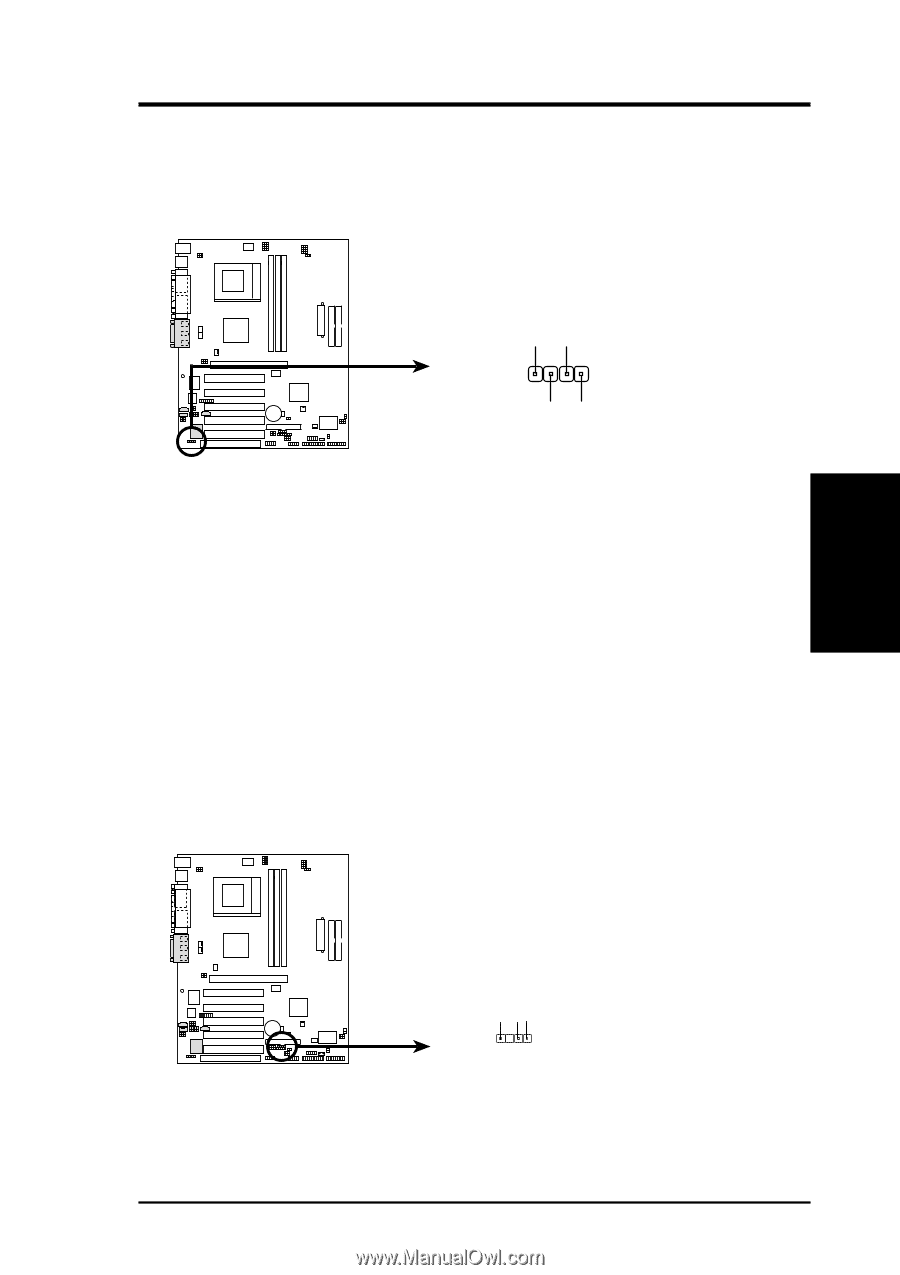
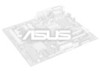
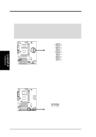
+5Volt (Power Supply Stand By) Chassis Signal Ground 3. H/W SETUP Connectors 01 01 01 01 01 01 3. HARDWARE SETUP 21) Digital Audio Interfaces (2-pin SPDIFOUT/CDSPDIFIN) (optional) These connectors connect SPDIF audio cable that allows digital instead of analog sound output from CD-ROM, DVD-ROM, CD-RW, and advanced sound cards such as SoundBlaster. Live. A7V266 A7V266 Digital Audio Interface GND GND SPDIFOUT SPDIFIN 22) Chassis Open Alarm Lead (4-pin CHASSIS) This lead is for a chassis designed for chassis intrusion detection. This requires an external detection mechanism such as a chassis intrusion monitor/sensor or microswitch. When any chassis component is removed, the sensor is triggered and a high-level signal is sent to this lead to record a chassis intrusion event.The event is then be processed by software such as LDCM. When not using the chassis intrusion lead, place a jumper cap over the pins to close the circuit. CHASSIS A7V266 1 A7V266 Chassis Open Alarm Lead ASUS A7V266 User's Manual 41
-
 1
1 -
2
-
3
-
4
-
5
-
6
-
7
-
8
-
9
-
10
-
11
-
12
-
13
-
14
-
15
-
16
-
17
-
18
-
19
-
20
-
21
-
22
-
23
-
24
-
25
-
26
-
27
-
28
-
29
-
30
-
31
-
32
-
33
-
34
-
35
-
 36
36 -
 37
37 -
 38
38 -
 39
39 -
 40
40 -
 41
41 -
 42
42 -
 43
43 -
 44
44 -
 45
45 -
 46
46 -
47
-
48
-
49
-
50
-
51
-
52
-
53
-
54
-
55
-
56
-
57
-
58
-
59
-
60
-
61
-
62
-
63
-
64
-
65
-
66
-
67
-
68
-
69
-
70
-
71
-
72
-
73
-
74
-
75
-
76
-
77
-
78
-
79
-
80
-
81
-
82
-
83
-
84
-
85
-
86
-
87
-
88
-
89
-
90
-
91
-
92
-
93
-
94
-
95
-
96
-
97
-
98
-
99
-
100
-
101
-
102
-
103
-
104
-
105
-
106
-
107
-
108
-
109
-
110
 |
 |