Asus A7V400-MX SE A7V400-MX SE user's manual for English version - Page 33
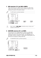
This connector is for a GAME/MIDI port. Connect the GAME/MIDI
 |
View all Asus A7V400-MX SE manuals
Add to My Manuals
Save this manual to your list of manuals |
Page 33 highlights
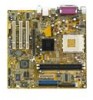
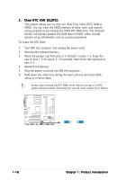
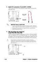
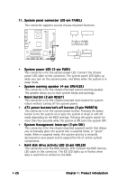
5 . USB connectors (10-1 pin USB56, USB78) These connectors are for USB 2.0 ports. Connect the USB module cable to any of these connectors, then install the module to a slot opening at the back of the system chassis. The USB module is purchased separately. USB+5V USB_P8USB_P8+ GND NC USB+5V USB_P6USB_P6+ GND NC USB+5V USB_P7USB_P7+ GND USB+5V USB_P5USB_P5+ GND A7V400-MX SE USB56 1 A7V400-MX SE USB connectors USB78 1 Never connect a 1 3 9 4 c a b l e to the USB connectors. Doing so will damage the motherboard! 6 . GAME/MIDI connector (16-1 pin GAME) This connector is for a GAME/MIDI port. Connect the GAME/MIDI module cable to this connector, then install the module to a slot opening at the back of the system chassis. The GAME/MIDI port on the module connects a joystick or a game pad for playing games, and MIDI devices for playing or editing audio files. The GAME/MIDI module is purchased separately. +5V J1B2 J1CY GND GND J1CX J1B1 +5V A7V400-MX SE GAME A7V400-MX SE Game connector ASUS A7V400-MX SE MIDI_IN J2B2 J2CY MIDI_OUT J2CX J2B1 +5V 1-23
-
 1
1 -
2
-
3
-
4
-
5
-
6
-
7
-
8
-
9
-
10
-
11
-
12
-
13
-
14
-
15
-
16
-
17
-
18
-
19
-
20
-
21
-
22
-
23
-
24
-
25
-
26
-
27
-
 28
28 -
 29
29 -
 30
30 -
 31
31 -
 32
32 -
 33
33 -
 34
34 -
 35
35 -
 36
36 -
 37
37 -
 38
38 -
39
-
40
-
41
-
42
-
43
-
44
-
45
-
46
-
47
-
48
-
49
-
50
-
51
-
52
-
53
-
54
-
55
-
56
-
57
-
58
-
59
-
60
-
61
-
62
-
63
-
64
-
65
-
66
-
67
-
68
-
69
-
70
-
71
-
72
 |
 |