Asus AP120R User Guide - Page 44
Optional components
 |
View all Asus AP120R manuals
Add to My Manuals
Save this manual to your list of manuals |
Page 44 highlights
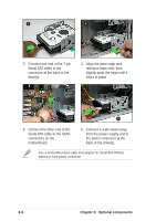
3 4 3. Connect one end of the 7-pin Serial ATA cable to the connector at the back of the drive(s). 4. Align the drive cage and retention base rails, then slightly push the cage until it clicks in place 5 6 5. Connect the other end of the Serial ATA cable to the SATA connectors on the motherboard. 6. Connect a 4-pin power plug from the power supply unit to the power connector at the back of the drive(s). Use a Serial ATA power cable and adapter for Serial ATA HDD(s) without a 4-pin power connector. 3-6 Chapter 3: Optional components
-
 1
1 -
2
-
3
-
4
-
5
-
6
-
7
-
8
-
9
-
10
-
11
-
12
-
13
-
14
-
15
-
16
-
17
-
18
-
19
-
20
-
21
-
22
-
23
-
24
-
25
-
26
-
27
-
28
-
29
-
30
-
31
-
32
-
33
-
34
-
35
-
36
-
37
-
38
-
 39
39 -
 40
40 -
 41
41 -
 42
42 -
 43
43 -
 44
44 -
 45
45 -
 46
46 -
 47
47 -
 48
48 -
 49
49 -
50
-
51
-
52
 |
 |
Chapter 3:
Optional components
3-6
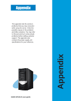
5.
Connect the other end of the
Serial ATA cable to the SATA
connectors on the
motherboard.
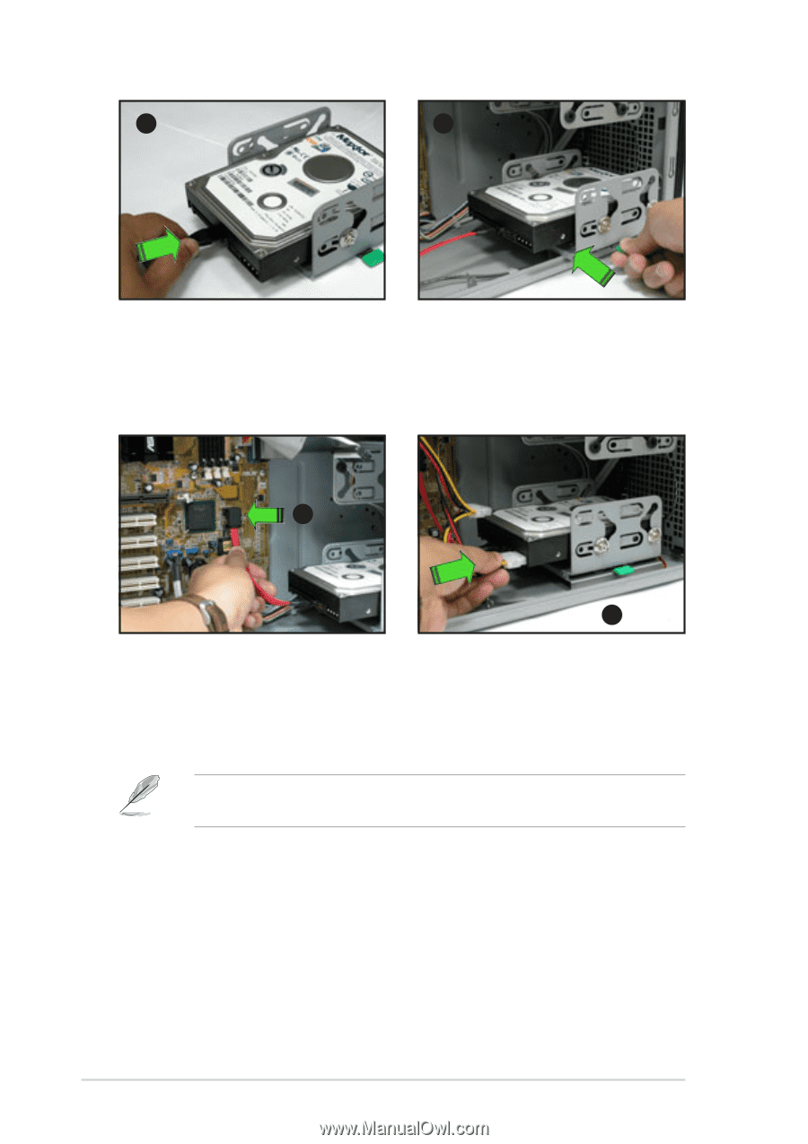
6.
Connect a 4-pin power plug
from the power supply unit to
the power connector at the
back of the drive(s).
5
6
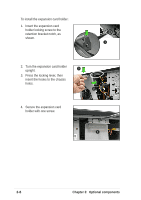
3.
Connect one end of the 7-pin
Serial ATA cable to the
connector at the back of the
drive(s).
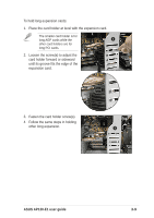
4.
Align the drive cage and
retention base rails, then
slightly push the cage until it
clicks in place
3
4
Use a Serial ATA power cable and adapter for Serial ATA HDD(s)
without a 4-pin power connector.