Asus AP2000 Hardware Reference - Page 18
Front Cooling Fan Control Board, Message LED Description
 |
View all Asus AP2000 manuals
Add to My Manuals
Save this manual to your list of manuals |
Page 18 highlights
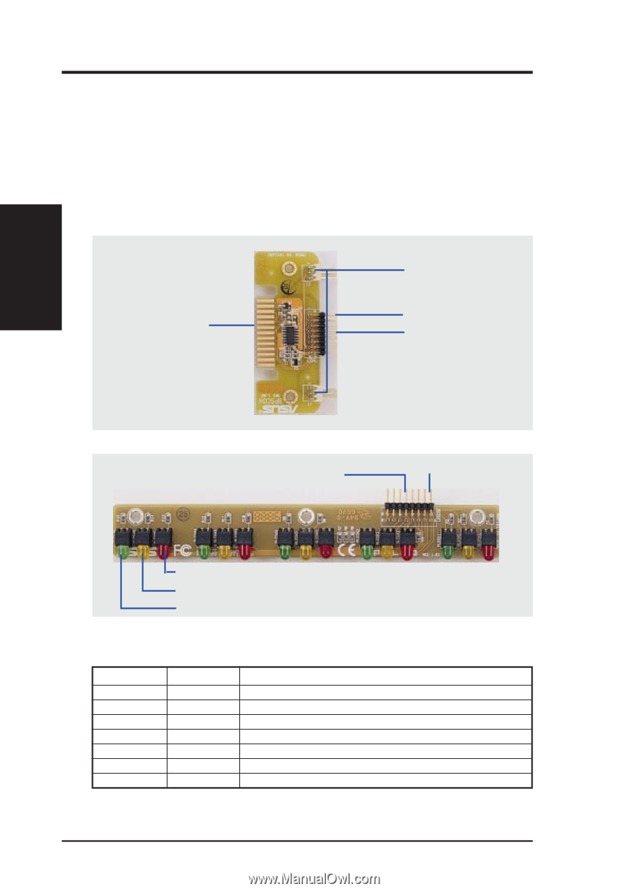
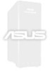
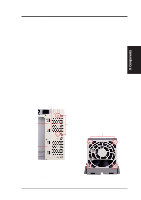
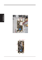
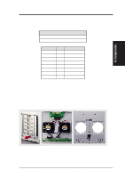
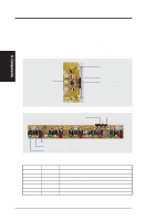
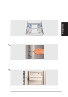
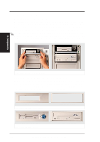
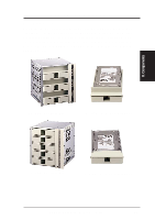
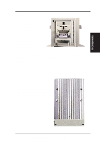
II. System Components Front Cooling Fan Control Board The front cooling fans' main purpose is to cool the hard disk drives. These fans also have a fan control board like the rear cooling fans. The front cooling fan module consists of a control board, a hard disk drive LED status board, and two cooling fans. The message LED board mounted in the front of the cooling fan module consists of five sets of LEDs to represent the status of up to five hard disk drives. Each set has three LEDs which shows the power, activity, and status of each hard disk drive. Gold Finger Connector to the SCSI Back plane Board 3-pin Fan Header pin 1 LED Board Header (For cable to connect to LED board) II. Components Front cooling fan control board LED Board Header pin 1 (For cable to connect to fan board) Hard drive Status LED (Red) Hard drive Access LED (Yellow) Hard drive Power LED (Green) Hard disk drive message board Message LED Description Power LED off on on on on fast flash fast flash Status LED Description off power subsystem OK and ready for hard drive insertion off Hard disk drive is OK for operation on Hard disk drive failure (*) fast flash RAID in rebuilding (*) slow flash Hot-spare hard disk drive (*) on Hard disk drive power failure/short circuit fast flash Fan failure * Must be provided by RAID controller's SAF-TE function. 18 AP2000 Hardware Reference Guide
-
 1
1 -
2
-
3
-
4
-
5
-
6
-
7
-
8
-
9
-
10
-
11
-
12
-
 13
13 -
 14
14 -
 15
15 -
 16
16 -
 17
17 -
 18
18 -
 19
19 -
 20
20 -
 21
21 -
 22
22 -
 23
23 -
24
-
25
-
26
-
27
-
28
-
29
-
30
-
31
-
32
-
33
-
34
-
35
-
36
-
37
-
38
-
39
-
40
 |
 |