Asus AP2000 Hardware Reference - Page 24
SCSI Backplane
 |
View all Asus AP2000 manuals
Add to My Manuals
Save this manual to your list of manuals |
Page 24 highlights
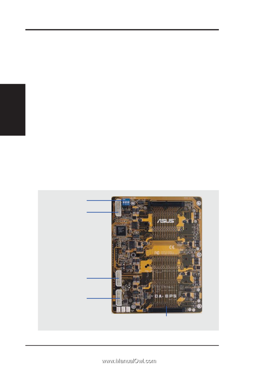
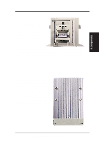
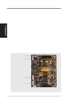
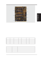
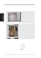
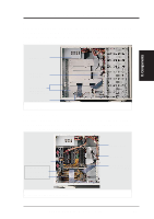
II. Components II. System Components SCSI Backplane The SCSI backplane of this server is comprised of one SCSI board with Ultra2 SCSI connectors, power inputs, and SCSI ID dip switches. This configuration allows Ultra2 SCSI SCA hard disk drives to be docked into the server using a SCA connector. SCSI Board Placement There are six screws on the SCSI board. The extended expansion card guide must be removed before the SCSI board can be removed. The SCSI board has one side with two connectors and three power connectors and another side with either three or five SCSI SCA connectors. Face the side with the power connector toward the motherboard. In order to ensure proper orientation of the SCSI board, the screw holes are not placed symmetrically. SCSI Board Power Installation There are three power connectors on the front side of the SCSI board. The PWR1 and PWR2 connectors have to be connected to the power supply, the PWR3 connector is a spare power connector which will supply power if PWR1 and/or PWR2 connectors fail to supply power. The voltage distribution for the three power connectors are not equal due to the enormous voltage and current requirements by the SCSI drives. SCSI ID Select DIP Switch PWR3 Connector PWR2 Connector PWR1 Connector The provided terminator must be placed on this bottom SCSI connector. 24 AP2000 Hardware Reference Guide
-
 1
1 -
2
-
3
-
4
-
5
-
6
-
7
-
8
-
9
-
10
-
11
-
12
-
13
-
14
-
15
-
16
-
17
-
18
-
 19
19 -
 20
20 -
 21
21 -
 22
22 -
 23
23 -
 24
24 -
 25
25 -
 26
26 -
 27
27 -
 28
28 -
 29
29 -
30
-
31
-
32
-
33
-
34
-
35
-
36
-
37
-
38
-
39
-
40
 |
 |