Asus AP2000 Hardware Reference - Page 20
Fixed Storage Devices
 |
View all Asus AP2000 manuals
Add to My Manuals
Save this manual to your list of manuals |
Page 20 highlights
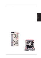
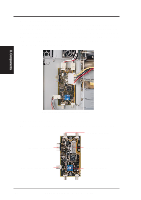
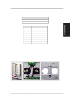
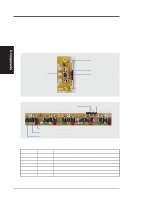
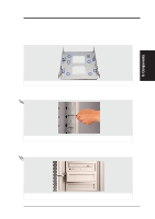
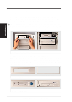
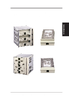
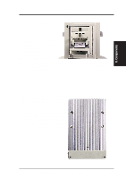
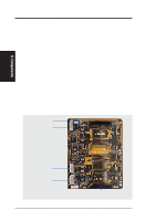
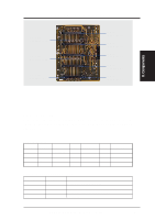
II. System Components Fixed Storage Devices Floppy Drive and CD-ROM The floppy drive fits in the topmost bay along with the power button. A CDROM can fit into either the second, third, or fourth bay from the top. A metal clip on each side of the device tray secures the tray in place. Press inward to release the clips. The tray slides in or out on the side rails. IMPORTANT: If using an IDE hard disk drive in this large chassis, it is recommended that only one is installed and with the shortest IDE cable possible. Long IDE cables will cause poor signal. Select "...PIO/DMA Mode : 3/1" in BIOS CHIPSET FEATURES SETUP for a more stable IDE operation. II. Components Removing a floppy or CD-ROM drive Floppy Drive and Storage Device Spacers Spacers are required for cosmetics only. A floppy drive spacer is used to cover the floppy drive and power button. A standard storage device spacer is used to cover the CD-ROM, tape drive, or additional CD-ROMs. You should purchase an extra spacer for each storage device. Floppy Drive Spacer Floppy and CD-ROM drive spacers Fixed Device Spacer Floppy drive with spacer Floppy and CD-ROM drives CD-ROM with spacer 20 AP2000 Hardware Reference Guide
-
 1
1 -
2
-
3
-
4
-
5
-
6
-
7
-
8
-
9
-
10
-
11
-
12
-
13
-
14
-
 15
15 -
 16
16 -
 17
17 -
 18
18 -
 19
19 -
 20
20 -
 21
21 -
 22
22 -
 23
23 -
 24
24 -
 25
25 -
26
-
27
-
28
-
29
-
30
-
31
-
32
-
33
-
34
-
35
-
36
-
37
-
38
-
39
-
40
 |
 |
