Asus AP7500 Hardware Reference Guide - Page 18
Hot-Swap Trays, Hot-Swap Tray Interface
 |
View all Asus AP7500 manuals
Add to My Manuals
Save this manual to your list of manuals |
Page 18 highlights
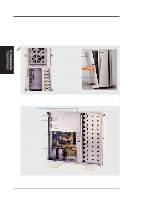
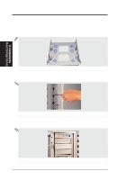
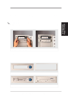
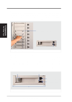
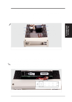
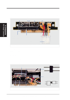
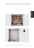
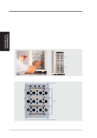
II. System Components Hot-Swap Trays Maximum uptime in a server requires devices that can be easily replaced or "swapped." The main hard disks are mounted in internal hot-swap trays for easy replacement. To remove the tray, unlock the tray and pull on the handle. A lock secures the handle and switches on or off the power to the hard drive. II. Components Hot-Swap Trays Hot-Swap Tray (8 Total) Hot-Swap Tray Keylock Positions Lock/ Power On Removing or inserting the hot-swap tray Unlock/ Power Off Hot-Swap Tray Interface The front of the hot-swap tray provides a keylock in order to switch the power on, which also locks the handle, and switch the power off, which also releases the handle. Two LEDs provide information on the power and activity status of the hard disk drive. When power is received by the hot-swap tray's connector board, the power LED will light. When data is written or read to or from the contained hard disk drive, the activity LED will flash proportional to the amount of data transferred. Air Activity LED Inlet (SLED) Keylock / Power Switch Power LED (PLED) Release / Transport Handle Hot-swap tray face plate 18 AP7500 Hardware Reference Guide
-
 1
1 -
2
-
3
-
4
-
5
-
6
-
7
-
8
-
9
-
10
-
11
-
12
-
 13
13 -
 14
14 -
 15
15 -
 16
16 -
 17
17 -
 18
18 -
 19
19 -
 20
20 -
 21
21 -
 22
22 -
 23
23 -
24
-
25
-
26
-
27
-
28
-
29
-
30
-
31
-
32
-
33
-
34
-
35
-
36
-
37
-
38
-
39
-
40
 |
 |
