Asus AP7500 Hardware Reference Guide - Page 26
Device Connections, Floppy Disk Drive 1.44MB
 |
View all Asus AP7500 manuals
Add to My Manuals
Save this manual to your list of manuals |
Page 26 highlights
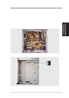
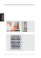
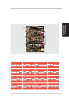
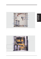
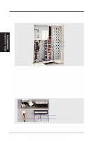
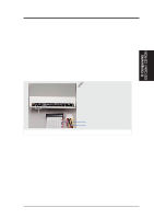
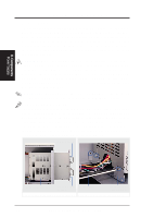
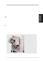
II. System Components Device Connections The following picture gives an example of how the server looks with all its cables connected to both standard and optional components. II. Components Connections / Floppy Plastic Keeper SCSI Cables Cables connected to devices Floppy Disk Drive (1.44MB) The 1.44MB floppy disk drive requires signal and power connections. The power connection is easy since it only fits one way and a latch is available to secure it when fully inserted. The signal cable is tricky because the cable fits in both orientations as well as shifted one direction or the other. The signal cable also has no latch to determine when full insertion is made. Align the red stripes of the signal and power cables so that they face each other. Carefully insert the connector while visually watching the progress so that proper alignment and insertion is made. 1.44MB floppy disk drive connections Red stripe of signal cable Red stripe of power cable 26 AP7500 Hardware Reference Guide
-
 1
1 -
2
-
3
-
4
-
5
-
6
-
7
-
8
-
9
-
10
-
11
-
12
-
13
-
14
-
15
-
16
-
17
-
18
-
19
-
20
-
 21
21 -
 22
22 -
 23
23 -
 24
24 -
 25
25 -
 26
26 -
 27
27 -
 28
28 -
 29
29 -
 30
30 -
 31
31 -
32
-
33
-
34
-
35
-
36
-
37
-
38
-
39
-
40
 |
 |
