Asus AP7500 Hardware Reference Guide - Page 30
Power Supply
 |
View all Asus AP7500 manuals
Add to My Manuals
Save this manual to your list of manuals |
Page 30 highlights
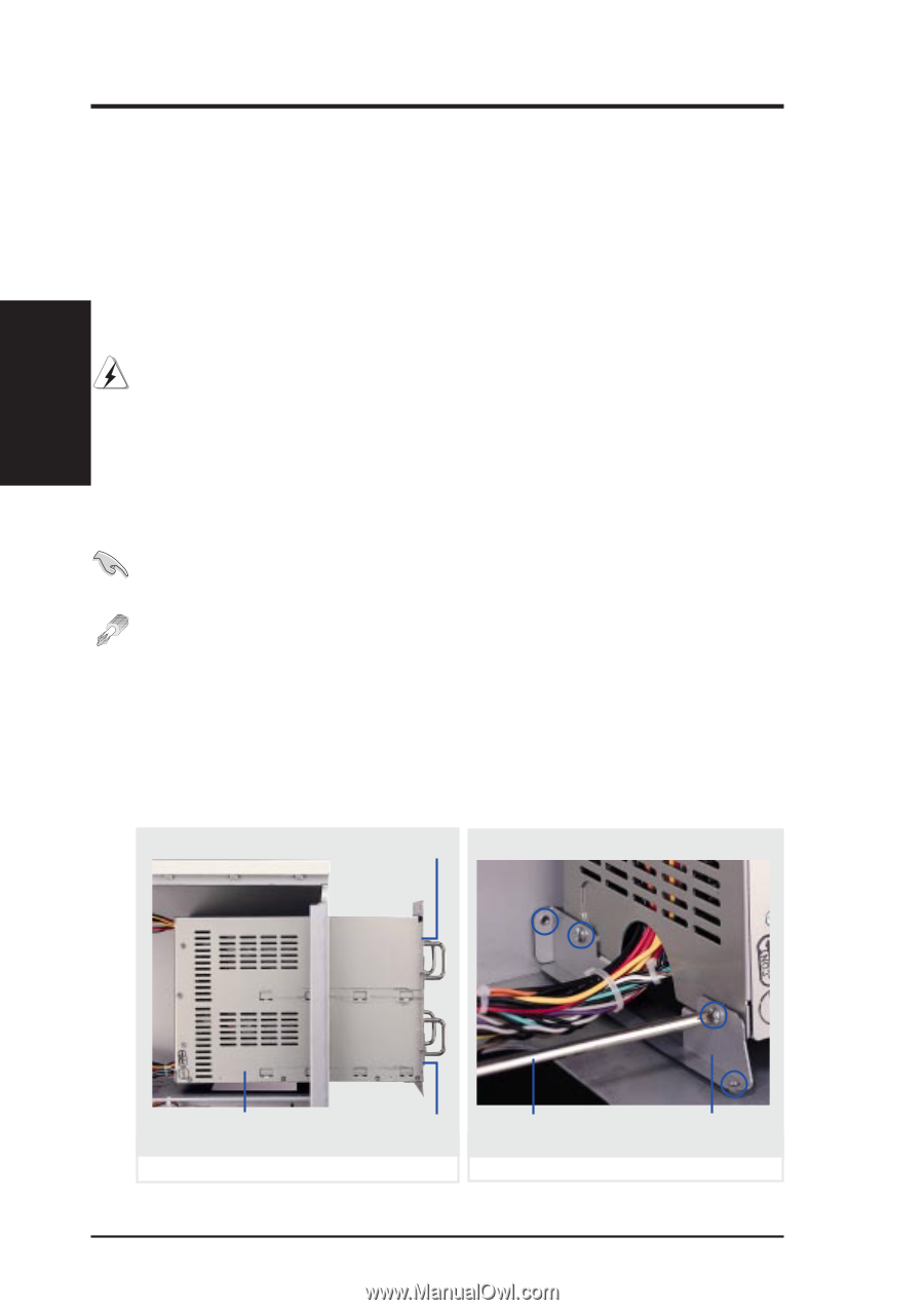
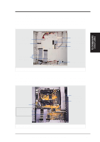
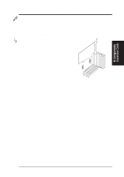
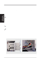
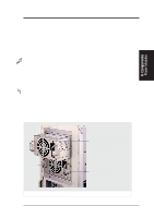
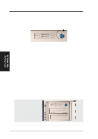
II. Components Power Supply II. System Components Power Supply This server has a special redundant power supply with specifications to surpass this server's requirements. A clearly marked label gives detailed specifications of the power supply. A power switch is not provided therefore it is necessary to remove the power cord before opening the side panel in order to shut off the standby power. With the power cord removed, you can ensure there are no voltages which can cause shorts while installing or removing internal components. CAUTION: Before turning ON your server for the first time, set the power supply's voltage. Some products may have auto voltage switching to accommodate 220V-240V or 110-120V but this power supply must be set manually. The factory default should be on 230V to accommodate the higher voltage but it is safer to visually inspect the switch yourself in case it is not. Using the power modules set on 115V in 230V environments may cause damage to the power modules. IMPORTANT: For countries using 110V-120V, you must slide the switch to 115V or else power up is not possible (but no damage will occur). Power Supply Mounting The redundant power supply is swappable within its own frame. Two screws secure the power supply in the inserted position. The entire frame can also be unscrewed for servicing if necessary. A support brace must be used to support the frame under the inner edge. The support brace can only be secured after the power supply frame is inserted and must be removed before the power supply frame is removed from the chassis. There are four screws securing the power supply support brace as circled below. Top power module Power supply frame Bottom power Screwdriver module Power supply support brace Power supply with frame halfway inserted Securing power supply support brace 30 AP7500 Hardware Reference Guide
-
 1
1 -
2
-
3
-
4
-
5
-
6
-
7
-
8
-
9
-
10
-
11
-
12
-
13
-
14
-
15
-
16
-
17
-
18
-
19
-
20
-
21
-
22
-
23
-
24
-
 25
25 -
 26
26 -
 27
27 -
 28
28 -
 29
29 -
 30
30 -
 31
31 -
 32
32 -
 33
33 -
 34
34 -
 35
35 -
36
-
37
-
38
-
39
-
40
 |
 |