Asus AP7500 Hardware Reference Guide - Page 31
Power Module Rating, Power Module Failure
 |
View all Asus AP7500 manuals
Add to My Manuals
Save this manual to your list of manuals |
Page 31 highlights
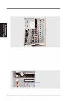
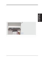
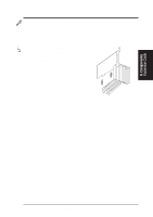
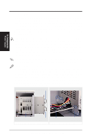
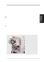
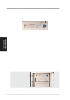
II. Components Power Modules II. System Components Power Module Rating The redundant power supply consist of one frame and two identical ATX power modules. The power supply must be turned on or off through an ATX power switch connected to the motherboard's panel connector. The power modules are rated at 400W each and have passive current sharing on all outputs. Each power module supplies up to 400W to share the load but do not provide 800W combined. If one power module fails, 400W load is supported using one power module. Power Module Failure If any of the power modules fail to provide a voltage on any of its outputs, an audible alarm (located in the frame) will sound and the failed power module's LED will turn OFF. The power module's status LED lights when both input and output voltages are stable and darkens if either the input or output voltages fail. If the alarm sounds, perform the following steps: 1. Remove the power cord to the failed power module (with dark LED). 2. Remove the two screws and slide the failed power module out. The alarm should stop. If not, there may be a problem with the other module or with the redundant power supply frame (very unlikely). 3. Reinsert the failed power module and plug in the AC cord to confirm. 4. If the alarm sounds again, remove the failed power module and replace it with a good one as soon as possible. Screw Status LED (lights when input/ output voltages are stable and darkens when either input or output voltages fail) Power module screw (one on each side) Top power module partially inserted AP7500 Hardware Reference Guide 31
-
 1
1 -
2
-
3
-
4
-
5
-
6
-
7
-
8
-
9
-
10
-
11
-
12
-
13
-
14
-
15
-
16
-
17
-
18
-
19
-
20
-
21
-
22
-
23
-
24
-
25
-
 26
26 -
 27
27 -
 28
28 -
 29
29 -
 30
30 -
 31
31 -
 32
32 -
 33
33 -
 34
34 -
 35
35 -
 36
36 -
37
-
38
-
39
-
40
 |
 |
