Asus CUR-DLSR CUR-DLSR User Manual - Page 36
ASUS CUR-DLSR User's Manual, Serial Port 2 Connector, Panel 2 Connector
 |
View all Asus CUR-DLSR manuals
Add to My Manuals
Save this manual to your list of manuals |
Page 36 highlights
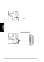
3. HARDWARE SETUP 11) Serial Port 2 Connector This motherboard has a second serial port connector to accommodate additional serial peripherals. See the BIOS section 4.4.2 I/O Device Configuration to configure Serial Port 2 settings. PIN 1 CUR-DLSR CUR-DLSR Serial COM2 Connector 12) Panel 2 Connector This connector supports some of the functions in the 20-pin PANEL connector, such as the power button, IDE LED, and power LED. ATX Power Button* 1 IDELED Power LED PWRBTN# GND IDELEDIDELED+ +5V PLED CUR-DLSR CUR-DLSR Panel 2 Connector * Requires an ATX power supply. 3. H/W SETUP Connectors 36 ASUS CUR-DLSR User's Manual
-
 1
1 -
2
-
3
-
4
-
5
-
6
-
7
-
8
-
9
-
10
-
11
-
12
-
13
-
14
-
15
-
16
-
17
-
18
-
19
-
20
-
21
-
22
-
23
-
24
-
25
-
26
-
27
-
28
-
29
-
30
-
 31
31 -
 32
32 -
 33
33 -
 34
34 -
 35
35 -
 36
36 -
 37
37 -
 38
38 -
 39
39 -
 40
40 -
 41
41 -
42
-
43
-
44
-
45
-
46
-
47
-
48
-
49
-
50
-
51
-
52
-
53
-
54
-
55
-
56
-
57
-
58
-
59
-
60
-
61
-
62
-
63
-
64
-
65
-
66
-
67
-
68
-
69
-
70
-
71
-
72
-
73
-
74
-
75
-
76
-
77
-
78
-
79
-
80
-
81
-
82
-
83
-
84
-
85
-
86
-
87
-
88
-
89
-
90
-
91
-
92
-
93
-
94
-
95
-
96
-
97
-
98
-
99
-
100
-
101
-
102
-
103
-
104
 |
 |

36
3. HARDWARE SETUP
ASUS CUR-DLSR User’s Manual
3. H/W SETUP
Connectors
11) Serial Port 2 Connector
This motherboard has a second serial port connector to accommodate additional
serial peripherals. See the BIOS section
4.4.2 I/O Device Configuration
to
configure Serial Port 2 settings.
12) Panel 2 Connector
This connector supports some of the functions in the 20-pin PANEL connector,
such as the power button, IDE LED, and power LED.
CUR-DLSR
CUR-DLSR Serial COM2 Connector
PIN 1
CUR-DLSR
CUR-DLSR Panel 2 Connector
+5V
GND
IDELED+
IDELED-
PLED
*
Requires an ATX power supply.
PWRBTN#
ATX Power
Button*
IDELED
Power LED
1