Asus CUR-DLSR CUR-DLSR User Manual - Page 37
ASUS CUR-DLSR User's Manual, Power Button Connector PWRBTN, ATX Power Connector, 24-pin block ATXPWR
 |
View all Asus CUR-DLSR manuals
Add to My Manuals
Save this manual to your list of manuals |
Page 37 highlights
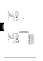
3. H/W SETUP Connectors 3. HARDWARE SETUP 13) ATX Power Connector (20/24-pin block ATXPWR) This connector connects to an ATX power supply. The plug from the power supply fits in only one orientation because of the different hole sizes. Find the proper orientation and push down firmly making sure that the pins are aligned. IMPORTANT: Make sure that your ATX power supply can supply at least 720mA on the +5-volt standby lead (+5VSB). You may experience difficulty in turning ON your system if your power supply cannot support the load. +3 Volts -12 Volts Ground PSON# Ground Ground Ground -5 Volts +5 Volts +5 Volts +5 Volts Ground +3 Volts +3 Volts Ground +5 Volts Ground +5 Volts Ground Power OK +5V Standby +12 Volts +12 Volts +3 Volts 1 CUR-DLSR CUR-DLSR ATX Power Connector 14) Power Button Connector (PWRBTN) This connector allows you to turn the system ON or OFF. The power LED lights up when the system is turned ON. CUR-DLSR CUR-DLSR Power Button Connector PWRBTN# GND PWRBTN 1 ASUS CUR-DLSR User's Manual 37
-
 1
1 -
2
-
3
-
4
-
5
-
6
-
7
-
8
-
9
-
10
-
11
-
12
-
13
-
14
-
15
-
16
-
17
-
18
-
19
-
20
-
21
-
22
-
23
-
24
-
25
-
26
-
27
-
28
-
29
-
30
-
31
-
 32
32 -
 33
33 -
 34
34 -
 35
35 -
 36
36 -
 37
37 -
 38
38 -
 39
39 -
 40
40 -
 41
41 -
 42
42 -
43
-
44
-
45
-
46
-
47
-
48
-
49
-
50
-
51
-
52
-
53
-
54
-
55
-
56
-
57
-
58
-
59
-
60
-
61
-
62
-
63
-
64
-
65
-
66
-
67
-
68
-
69
-
70
-
71
-
72
-
73
-
74
-
75
-
76
-
77
-
78
-
79
-
80
-
81
-
82
-
83
-
84
-
85
-
86
-
87
-
88
-
89
-
90
-
91
-
92
-
93
-
94
-
95
-
96
-
97
-
98
-
99
-
100
-
101
-
102
-
103
-
104
 |
 |
