Asus H170I-PRO/CSM User Guide - Page 11
DDR4 DIMM slots, Intel, LGA1151 CPU socket, To erase the RTC RAM, Clear RTC RAM 2-pin CLRTC
 |
View all Asus H170I-PRO/CSM manuals
Add to My Manuals
Save this manual to your list of manuals |
Page 11 highlights
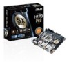
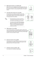
• We recommend that you use an EATX 12V Specification 2.0‑compliant power supply unit (PSU) with a minimum of 300W power rating. This PSU type has 24-pin and 8-pin power plugs. EATX12V PIN 1 +12V DC +12V DC GND GND • DO NOT forget to connect the 4-pin EATX +12V power plug. Otherwise, the system will not boot up. • We recommend that you use a PSU with higher power output when configuring a system with more power-consuming devices or when you intend to install additional devices. The system may become unstable or may not boot up if the power is inadequate. EATXPWR +3 Volts +12 Volts +12 Volts +5V Standby Power OK GND +5 Volts GND +5 Volts GND +3 Volts +3 Volts PIN 1 GND +5 Volts +5 Volts +5 Volts -5 Volts GND GND GND PSON# GND -12 Volts +3 Volts • If you are uncertain about the minimum power supply requirement for your system, refer to the Recommended Power Supply Wattage Calculator at http://support.asus.com/ PowerSupplyCalculator/PSCalculator.aspx?SLanguage=en-us for details. 3. Intel® LGA1151 CPU socket This motherboard comes with a surface mount LGA1151 socket designed for the 6th Generation Intel(R) Core(TM) i7/ Core(TM) i5/ Core(TM) i3, Pentium(R) and Celeron(R) processors. For more details, refer to Central Processing Unit (CPU). 4. Clear RTC RAM (2-pin CLRTC) This header allows you to clear the Real Time Clock (RTC) RAM in CMOS. You can clear the CMOS memory of date, and system setup parameters by erasing the CMOS RTC RAM data. The onboard button cell battery powers the RAM data in CMOS, which include system setup information such as system passwords. To erase the RTC RAM: 1. Turn OFF the computer and unplug the power cord. 2. Use a metal object such as a screwdriver to short the two pins. 3. Plug the power cord and turn ON the computer. 4. Hold down the key during the boot process and enter BIOS setup to re-enter data. +3V_BAT GND CLRTC PIN 1 If the steps above do not help, remove the onboard battery and short the two pins again to clear the CMOS RTC RAM data. After clearing the CMOS, reinstall the battery. 5. DDR4 DIMM slots Install 2 GB, 4 GB, 8 GB, and 16 GB unbuffered non-ECC DDR4 DIMMs into these DIMM sockets. For more details, refer to System memory. ASUS H170I-PRO 1-3
-
 1
1 -
2
-
3
-
4
-
5
-
 6
6 -
 7
7 -
 8
8 -
 9
9 -
 10
10 -
 11
11 -
 12
12 -
 13
13 -
 14
14 -
 15
15 -
 16
16 -
17
-
18
-
19
-
20
-
21
-
22
-
23
-
24
-
25
-
26
-
27
-
28
-
29
-
30
-
31
-
32
-
33
-
34
-
35
-
36
-
37
 |
 |
