Asus H170I-PRO/CSM User Guide - Page 13
IRQ assignments for this motherboard, USB 3.0 connector 20-1 pin USB3_12, M.2 socket 3
 |
View all Asus H170I-PRO/CSM manuals
Add to My Manuals
Save this manual to your list of manuals |
Page 13 highlights
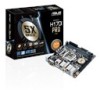
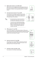
Never connect a 1394 cable to the USB connectors. Doing so will damage the motherboard! 10. USB 3.0 connector (20-1 pin USB3_12) This connector allows you to connect a USB 3.0 module for additional USB 3.0 front or rear panel ports. With an installed USB 3.0 module, you can enjoy all the benefits of USB 3.0 including faster data transfer speeds of up to 5Gbps, faster charging time for USB-chargeable devices, optimized power efficiency and backward compatibility with USB 2.0. USB3_12 GND IntA_P1_D+ IntA_P1_D- GND IntA_P1_SSTX+ IntA_P1_SSTX- GND IntA_P1_SSRX+ IntA_P1_SSRX- USB3+5V PIN 1 IntA_P2_D+ IntA_P2_DGND IntA_P2_SSTX+ IntA_P2_SSTXGND IntA_P2_SSRX+ IntA_P2_SSRXUSB3+5V 11. M.2 socket 3 This socket allows you to install an M.2 (NGFF) SSD module. • This socket supports M Key and 2242/2260/2280 storage devices. • When the M.2 Socket 3 is operating in SATA mode, SATA port 1 will be disabled. • M.2 Socket and PCIe X16_2 connector support PCIe mode and share bandwidth. By default, the device detection priority of the system is as follows: SATA Mode M.2 > PCIe X16_2 connector. • When using Intel® Desktop Responsiveness technologies with PCIe M.2 device, ensure to set up the Windows® UEFI operating system under RAID mode. M.2(SOCKET3) 12. PCI Express 3.0/2.0 x16 slot This motherboard supports one PCI Express 3.0/2.0 x16 graphic card that comply with the PCI Express specifications. IRQ assignments for this motherboard VGA USB 3.0 Controller SATA Controller HD Controller Intel LAN Realtek 8111H lan A B C D shared - - - shared - - - shared - - - shared - - - shared - - - - - shared - When using PCI cards on shared slots, ensure that the drivers support "Share IRQ" or that the cards do not need IRQ assignments. Otherwise, conflicts will arise between the two PCI groups, making the system unstable and the card inoperable. ASUS H170I-PRO 1-5
-
 1
1 -
2
-
3
-
4
-
5
-
6
-
7
-
 8
8 -
 9
9 -
 10
10 -
 11
11 -
 12
12 -
 13
13 -
 14
14 -
 15
15 -
 16
16 -
 17
17 -
 18
18 -
19
-
20
-
21
-
22
-
23
-
24
-
25
-
26
-
27
-
28
-
29
-
30
-
31
-
32
-
33
-
34
-
35
-
36
-
37
 |
 |
