Asus H170I-PRO/CSM User Guide - Page 12
IntelR H170 Serial ATA 6Gb/s connectors 7 pin SATA6G_3~6, SATAEXPRESS, System power LED 2-pin PWR_LED
 |
View all Asus H170I-PRO/CSM manuals
Add to My Manuals
Save this manual to your list of manuals |
Page 12 highlights
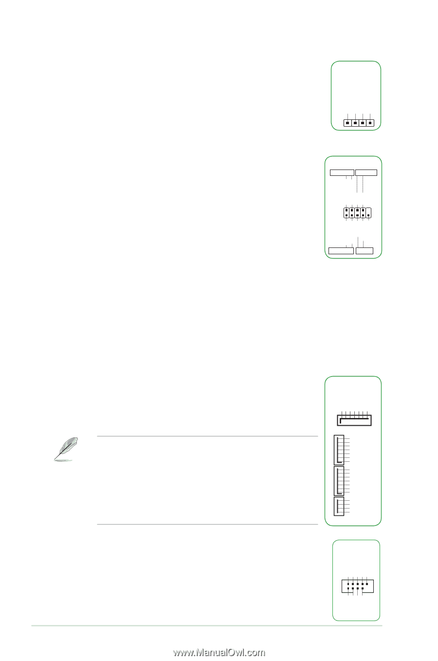
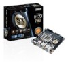
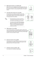
6. Speaker connector (4-pin SPEAKER) The 4-pin connector is for the chassis-mounted system warning speaker. The speaker allows you hear system beeps and warnings. SPEAKER +5V GND GND Speaker Out PIN 1 7. System panel connector (10-1 pin F_PANEL) This connector supports several chassis-mounted functions. • System power LED (2-pin PWR_LED) F_PANEL +PWR LED PWR BTN PWR_LED+ PWR_LEDPWR GND This 2-pin connector is for the system power LED. Connect the chassis power LED cable to this connector. The system power LED lights up when you turn on the system power, and blinks when the system is in sleep mode. PIN 1 HDD_LED+ HDD_LED- Ground HWRST# (NC) • Hard disk drive activity LED (2-pin HDD_LED) This 2-pin connector is for the HDD Activity LED. Connect the HDD Activity LED cable to this connector. The HDD LED lights up or flashes when data is read from or written to the HDD. +HDD_LED RESET • ATX power button/soft-off button (2-pin PWR_BTN) This connector is for the system power button. • Reset button (2-pin RESET) This 2-pin connector is for the chassis-mounted reset button for system reboot without turning off the system power. 8. Intel(R) H170 Serial ATA 6Gb/s connectors (7 pin SATA6G_3~6, SATAEXPRESS) These connectors connect to Serial ATA 6.0 Gb/s hard disk drives via Serial ATA 6.0 Gb/s signal cables. SATA6G GND RSATA_RXP4 RSATA_RXN4 GND RSATA_TXN4 RSATA_TXP4 GND If you installed Serial ATA hard disk drives, you can create a RAID 0, 1, 5, and 10 configuration with the Intel® Rapid Storage Technology through the onboard Intel® H170 chipset. • These connectors are set to [AHCI] by default. If you intend to create a Serial ATA RAID set using these connectors, set the SATA Mode item in the BIOS to [RAID]. • Before creating a RAID set, refer to the manual bundled in the motherboard support DVD. • The SATA EXPRESS connector can support one SATA Express device or two SATA devices. GND RSATA_TXP1 RSATA_TXN1 GND RSATA_RXN1 RSATA_RXP1 GND GND RSATA_TXP2 RSATA_TXN2 GND RSATA_RXN2 RSATA_RXP2 GND Floating Device_Reset GND Detection SATAEXPRESS USB+5V USB_P11USB_P11+ GND NC 9. USB 2.0 connector (10-1 pin USB910, USB1112) This connector is for USB 2.0 ports. Connect the USB module cable to any of this connector, then install the module to a slot opening at the back of the system chassis. These USB connectors comply with USB 2.0 specifications and supports up to 480Mbps connection speed. USB1112 PIN 1 USB+5V USB_P12USB_P12+ GND 1-4 Chapter 1: Product introduction
-
 1
1 -
2
-
3
-
4
-
5
-
6
-
 7
7 -
 8
8 -
 9
9 -
 10
10 -
 11
11 -
 12
12 -
 13
13 -
 14
14 -
 15
15 -
 16
16 -
 17
17 -
18
-
19
-
20
-
21
-
22
-
23
-
24
-
25
-
26
-
27
-
28
-
29
-
30
-
31
-
32
-
33
-
34
-
35
-
36
-
37
 |
 |